UC Series Quick Start Guide
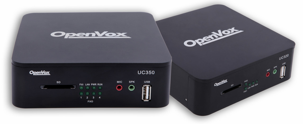
1.Appearance
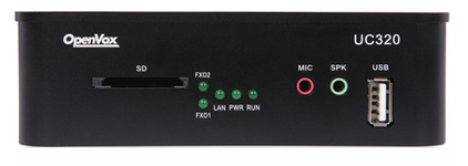
Figure 1-1-1 UC300A11EM1 front panel
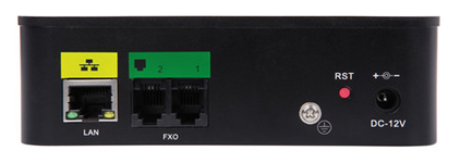
Figure 1-1-2 UC300A11EM1 back panel
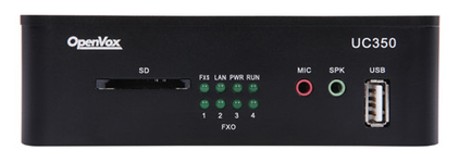
Figure 1-1-3 UC300A14EM1 front panel

Figure 1-1-4 UC300A14EM1 back panel
2.Description of account and ports
Website login
Default IP: 172.16.101.1
Username: admin
Password: admin
Sip account (10 accounts)
Username: 101~110
Password: pbx101~pbx110
UC300-A41EM port
fxs:port5 connects to analog telephony
fxo:port1~port4 connect to outside telephone connection
3.Device connection
FXS port connects to analog telephony, FXO connects to outside telephone connection.
4. Access to device
Log in to the Web GUI
Step 1 Use a CAT5 cable to connect the device to the local network where the PC is connected, or connect the device directly to the PC.
Step 2 Dial “**89” to obtain device IP address by an analog telephone, the device defaults to a fixed IP address: 172.16.101.1
Step 3 Make sure that the PC and the device are on the same network segment.
Step 4 Enter the device IP address in the browser address bar (e.g. 192.168.2.218);
Step 5 You can enter the login interface for device configuration by selecting your role and entering a password on the login interface. The default administrator password is admin.
Getting Started
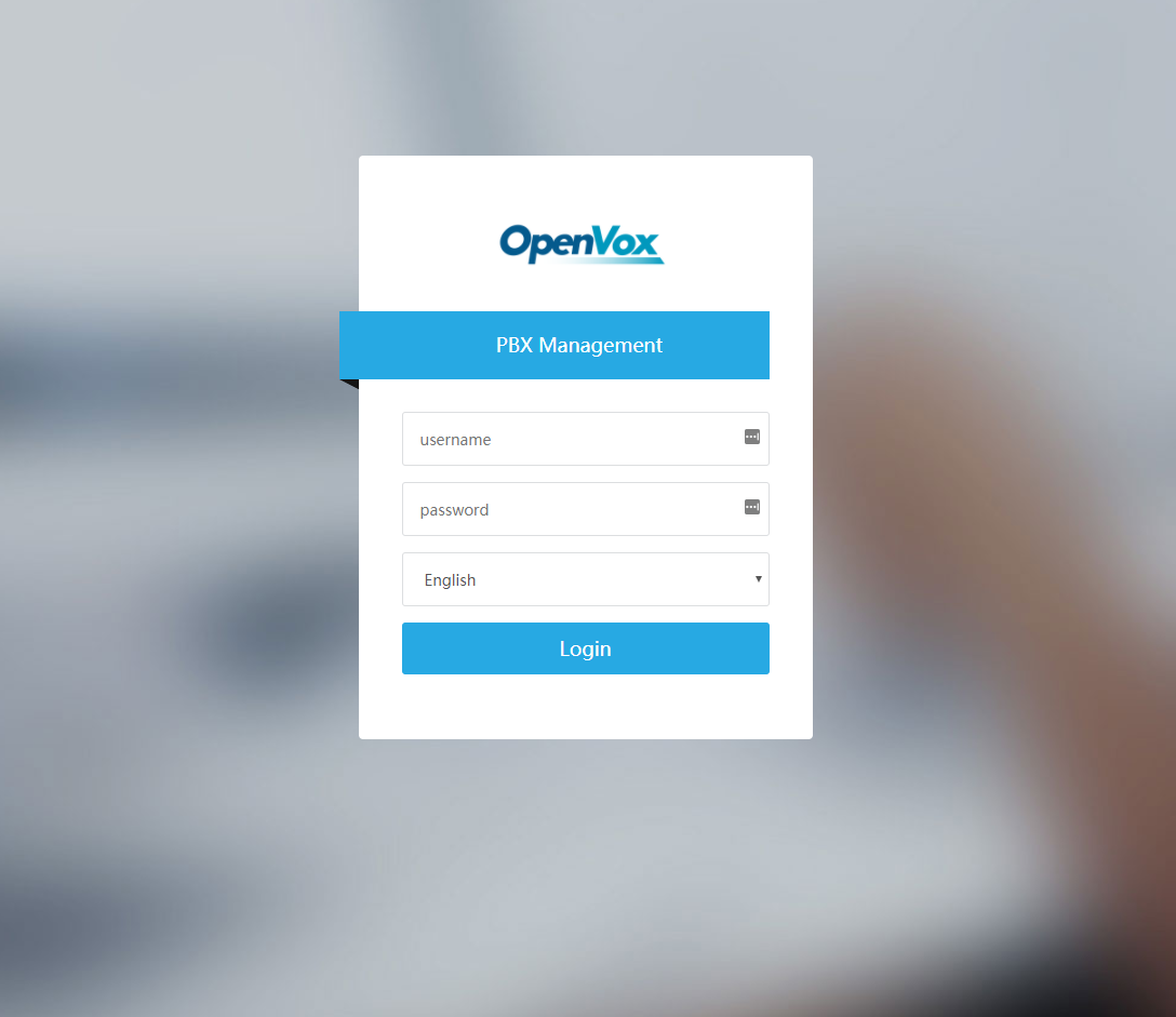
Figure 4-1 Login interface
Type in the default username: admin, and default password: admin to login.
5. Function setting
1) Reboot&Reset
This option allows for the rebooting and resetting of the IP-PBX series. Upon choosing whichever of the two options, you will be prompted to confirm the action.
Navigate to System > Maintenance > Reboot&Reset.
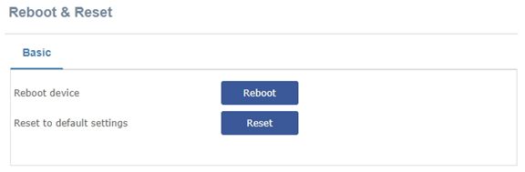
Figure 5-1 Reboot&Reset Interface
2) Language
The option “Language” of the Menu “Preferences” in UC Series lets us configure the language for the UC Series Web Interface.
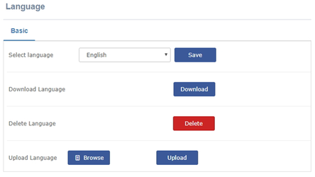
Figure 5-2 Language setting
3) Add extensions
By default, UC Series has registered 10 sip extensions, you can use sip phone to register directly.
Username: 101~110
Password: pbx101~pbx110
For instance, add FXS extensions(222) to the FXS port, navigate to PBX>Extensions > Extensions, click “Add extension”, choose Generic DAHDI Device in the Device, then click “submint”.
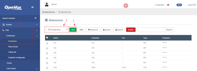
Figure 5-3 add an extension setting
The configurations interface as bellow:
User extension: 2000
Display Name: FXS
Channel : FXS-2
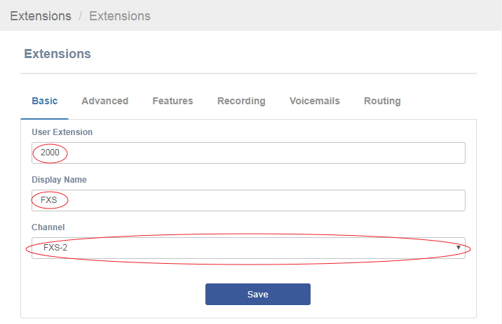
Figure 5-4 FXS extensions basic setting
4) Add sip trunk
Navigate to PBX>Trunks, click “Add SIP Trunk”.
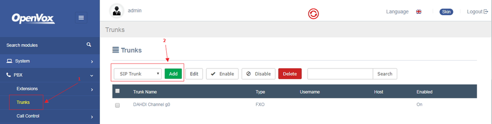
Figure 5-5 Add sip trunk interface
Enter the following configuration as below, in this case, the IP of service 2 is 172.16.101.2.
Table 5-1 2 service sip connections
UC | host=172.16.101.2 type=friend context=from-trunk username=8000 secret=8000 qualify=0 insecure=invite,port canreinvite=no Fromuser=8000 |
Service 2 | host=172.16.101.1 type=friend context=from-trunk username=8000 secret=8000 qualify=0 insecure=invite,port canreinvite=no Fromuser=8000 |
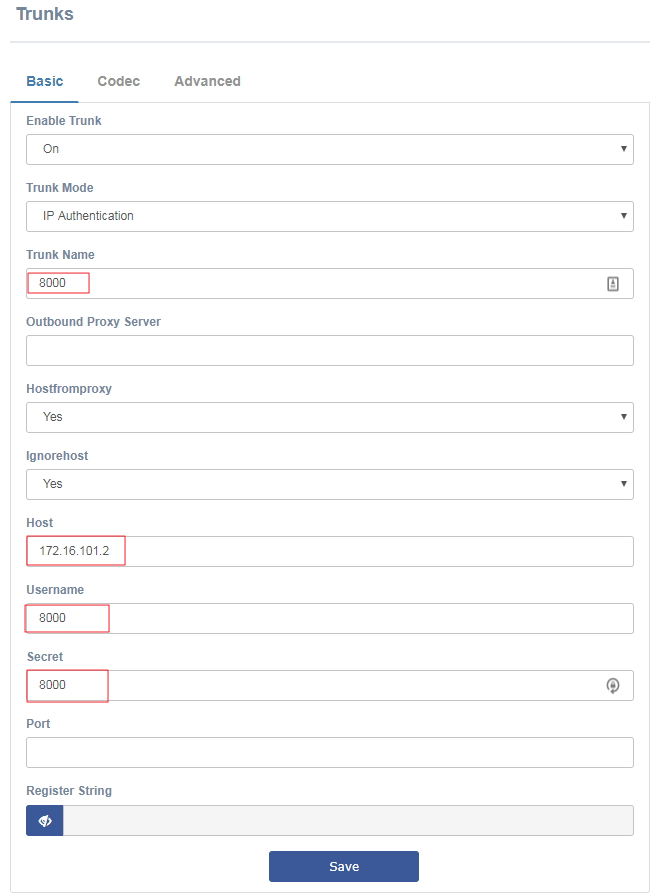
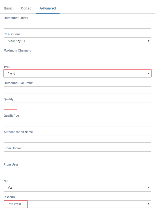
Figure 5-6 UC Series add sip trunk interface
5) Queue
Navigate to PBX> Call Features >Queue, adding a queue, static agents are assumed to always be in the extension of queue but not be supposed login the queue, and can’t log out of the queue. The dynamic member is an extension or callback number that can log in and out of the queue, you can use the Quick Extension Pick feature set an extension to a static / dynamic agent quickly.
After finish setting, user extensions can dial queue number (600) to join the queue directly. The static members that have been set, such as the 101 extension, you can directly dial the shortcut key (* 45) to join the queue.
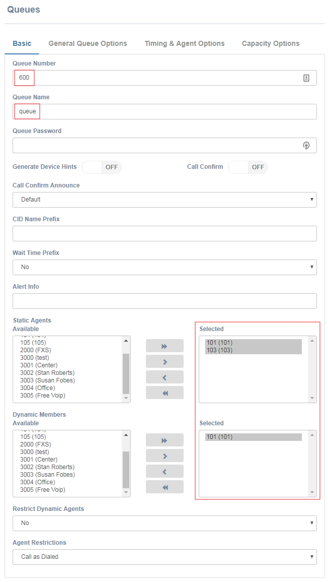
Figure 5-7 Add queue interface
6) Add Conference
Navigate to PBX> Call Features >Conference, add a external conference, user extensions can dial conference number (700) to join the conference directly.
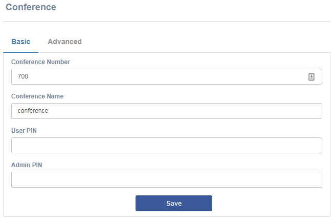
Figure 5-8 Add conference interface
7) Add IVR
Navigate to PBX>Call Features >IVR, add an IVR.
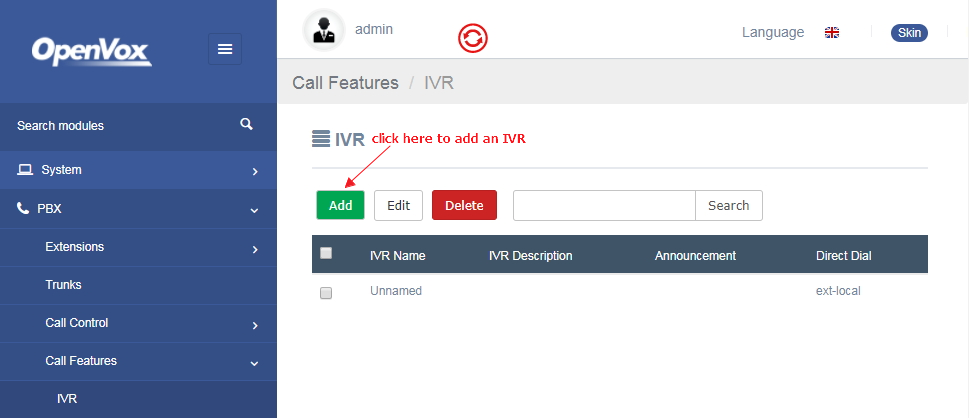
Figure 5-9 IVR interface
Function Description: Press 1 to go to the fxs extension; press 2 to go to the queue, press 3 to join the meeting. In this setup, hang-up directly on illegal input and timeout input.
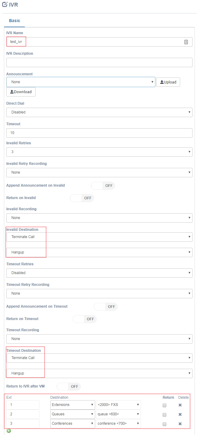
Figure 5-10 Add IVR interface
8) Outbound Routes
UC Series has set a outbound route begin with 9, which by FXO outbound.
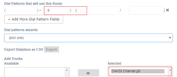
Figure 5-11 Outbound Route interface
Similarly, you can also create a new outbound begin with 8, to call to the sip trunk. Put"." to the match pattern is recommended.
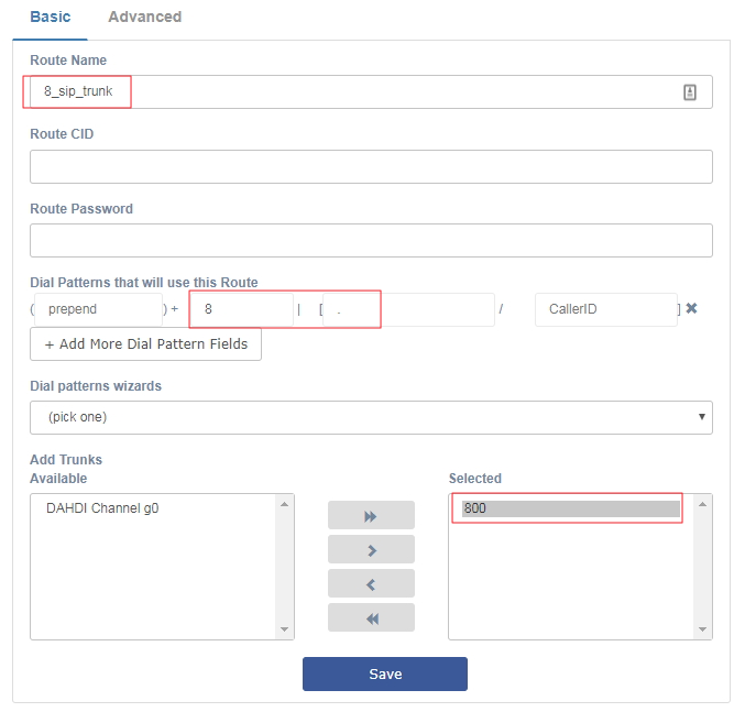
Figure 5-12 Outbound Route interface
9) Inbound Routes
The incoming calls to the UC Series system, connects to distance, which can be chosen by yourself. A typical example is that you can set all of the incoming calls on an FXO or FXS port on your UC Series to a specific extension, ring group, voicemail, etc. Other routes that are not specifically configured can use the global incoming route for incoming control.
The following figure shows how an incoming call can be routed to the IVR and transferred to the appropriate destination via the IVR (press1 go to the FXS analog trunk; press 2 go to the queue; press 3 go to the conference).
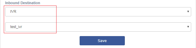
Figure 5-13 Inbound Route interface
6 Call
1) Internal Call
The internal extension user can dial the other party's extension number directly to establish a conversation. For example, the sip extension 101 dial 222 can make a conversation with the dahdi extension (analog telephone).
2) Outgoing call
An extension user needs to add put 9 as prefix to the number before exiting via FXO port. For example: dial 9 + your phone number, you can make a call to your phone.
Similarly, you can dial a number begin with 8, communicating to server B. The rules for outgoing routing can be found in the "Outgoing Routing" section.
3) Incoming call
Use the mobile phone or landline dial outside the number directly, according to the incoming routing rules to IVR, press1 go to the FXS analog trunk; press 2 go to the queue; press 3 go to the conference, this feature will be achieved in the end. The rules for outgoing routing can be found in the "Inbound Routes" section.