UC Series User Manual(For Version 4.0)

OpenVox Communication Co., Ltd
UC Series User Manual
Version 4.0
Address: 10/F, Building 6-A, Baoneng Science and Technology Industrial Park, Longhua New District, Shenzhen, Guangdong, China 518109
Tel: +86-755-66630978, 82535461, 82535362
Business Contact: sales@openvox.cn
Technical Support: support@openvox.cn
Business Hours: 09:00-18:00(GMT+8) from Monday to Friday
URL: www.openvox.cn
Thank You for Choosing OpenVox Products!
Revision History
Issue version | Issue date | Detail of change |
4.0 | Nov.18.2020 | Apply to the new version 4.2.0 UC series operating system firmware |
3.0 | May. 07, 2020 | Apply to the new version 4.1.0 UC series operating system firmware |
2.0 | Nov. 08, 2017 | Apply to the new UI 2.0 version |
1.2 | May. 25, 2017 | Apply to all UC series IPPBX |
1.1 | Dec. 05, 2016 | Release notes for 1.1.3,2.4 |
1.0 | Jun. 30, 2016 | Initial |
Copyright
Copyright© 2020 OpenVox Inc. All rights reserved. No part of this document may be reproduced without prior written permission.
Confidentiality
Information contained herein is of a highly sensitive nature and is confidential and proprietary to OpenVox Inc. No part may be distributed, reproduced or disclosed orally or in written form to any party other than the direct recipients without the express written consent of OpenVox Inc.
Disclaimer
OpenVox Inc. reserves the right to modify the design, characteristics, and products at any time without notification or obligation and shall not be held liable for any error or damage of any kind resulting from the use of this document.
OpenVox has made every effort to ensure that the information contained in this document is accurate and complete; however, the contents of this document are subject to revision without notice. Please contact OpenVox to ensure you have the latest version of this document.
Statement
This document applies to all UC series IPPBX, including UC300/UC500/UC501. Different types of IPPBXs may have functional differences. For details, please contact OpenVox sales or technical support.
Trademarks
All other trademarks mentioned in this document are the property of their respective owners.
1 Overview
1.1 Introduction
The UC series IPPBX delivers a multi-functional business office telephony system designed for small to medium enterprises. The series integrates functions such as IP phone, fax, and voice recording, and is compatible with multiple service platforms such as Cisco CallManager, BroadSoft, Huawei IMS and Asterisk, and terminals. The products are highly reliable, easy to install and deploy, and offer a brand-new experience in mobile offices and communications.
In addition, UC series IPPBX supports a wide selection of codecs and signaling protocols, including G711 (alaw/ulaw), G722, OPUS, AMR-NB/WB, SILK, G723.1 G726, G729, GSM, ADPCM, iLBC, H263, H263P, H264, VP8. Taking full advantage of open-source platform, the UC Series appliances support industry standard SIP trunks, IAX2 trunks, analog PSTN trunks, and analog station trunks.
The UC series delivers a full-featured IP Telephony solution. By supporting intelligent communication functions such as mobile phone extensions, instant multi-party conferences, call history, click-to-dial, and customer information management, it not only facilitates seamless communication between enterprise employees and customers, but also provides a solid basis for enterprises to analyze core business data.
1.2 Series of Products
1.2.1 UC300/500
The UC 300/500 series is made of aluminum and the fanless exquisite enclosed design provides important dust and moth protection. It can be operated in harsh industrial environments with ease.
The UC 300/500 series offers 2-8 analog port with up to 300 simultaneous calls in one single device, supports up to 86,000 minutes of recording and voicemail (.gsm), and supports failover in combination with FXS and FXO modules.
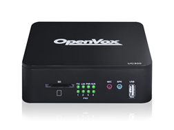
Figure 1-2-1 UC300
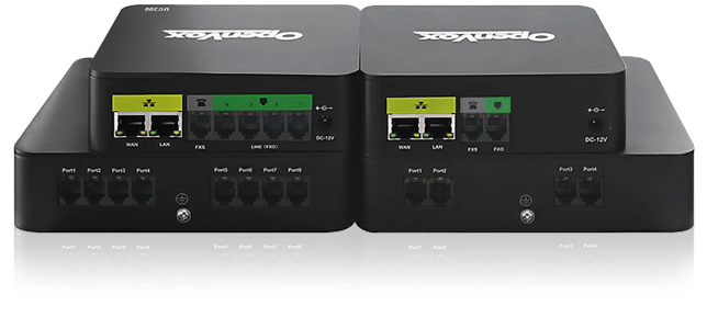
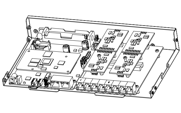
1.2.2 UC501
UC501 IPPBX is an upgraded version of UC500. It can be pre-installed with OpenVox IPPBX system or other open-source communication system chosen by customers. It has built-in Uninterruptible Power Supply (UPS) and full PBX functions to meet different usage scenarios.
The UC501 is equipped with up to 8 analog ports and 2 Ethernet interfaces for seamlessly integrating VoIP trunks and your existing PSTN lines. In addition, the UC501 is modular in design, equipped with 1FXO/1FXS/4FXO/4FXS modules, and with a detachable chassis, users can easily change the port type or expand the system.
Figure 1-2-2 UC501
1.3 Model
1.3.1 UC300/500 Series Model
UC300/500 series supports multiple models with varying amounts of FXO ports and FXS ports, as shown in the Table 1-1-2.
Table 1-1-2 Product Models
Mode | Network port | FXS Ports | FXO Ports | USB | SD | UPS |
UC300-A11EM1 | 1 x 10/100M Ethernet | 1 | 1 | 1 | 1 | NO |
UC300-A14EM1 | 1 x 10/100M Ethernet | 1 | 4 | 1 | 1 | NO |
UC300-A02EM1 | 1 x 10/100M Ethernet | 0 | 2 | 1 | 1 | NO |
UC300-A11EM1 | 2 x 10/100M Ethernet | 1 | 1 | 1 | 1 | YES |
UC300-A14EM2 | 2 x 10/100M Ethernet | 1 | 4 | 1 | 1 | YES |
UC300-A02EM2 | 2 x 10/100M Ethernet | 0 | 2 | 1 | 1 | YES |
UC500-A22EM2 | 2 x 10/100M Ethernet | 2 | 2 | 1 | 1 | YES |
UC500-A44EM2 | 2 x 10/100M Ethernet | 4 | 4 | 1 | 1 | YES |
UC500-A08EM2 | 2 x 10/100M Ethernet | 0 | 8 | 1 | 1 | YES |
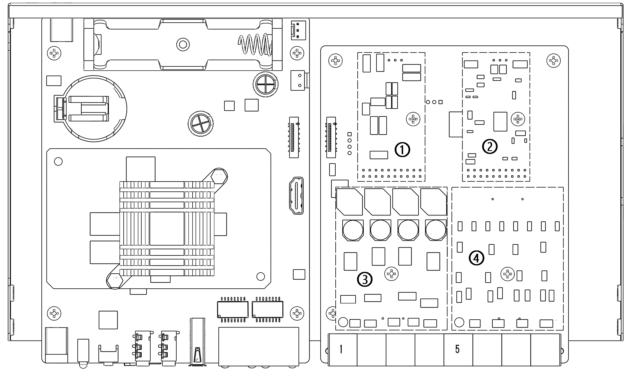
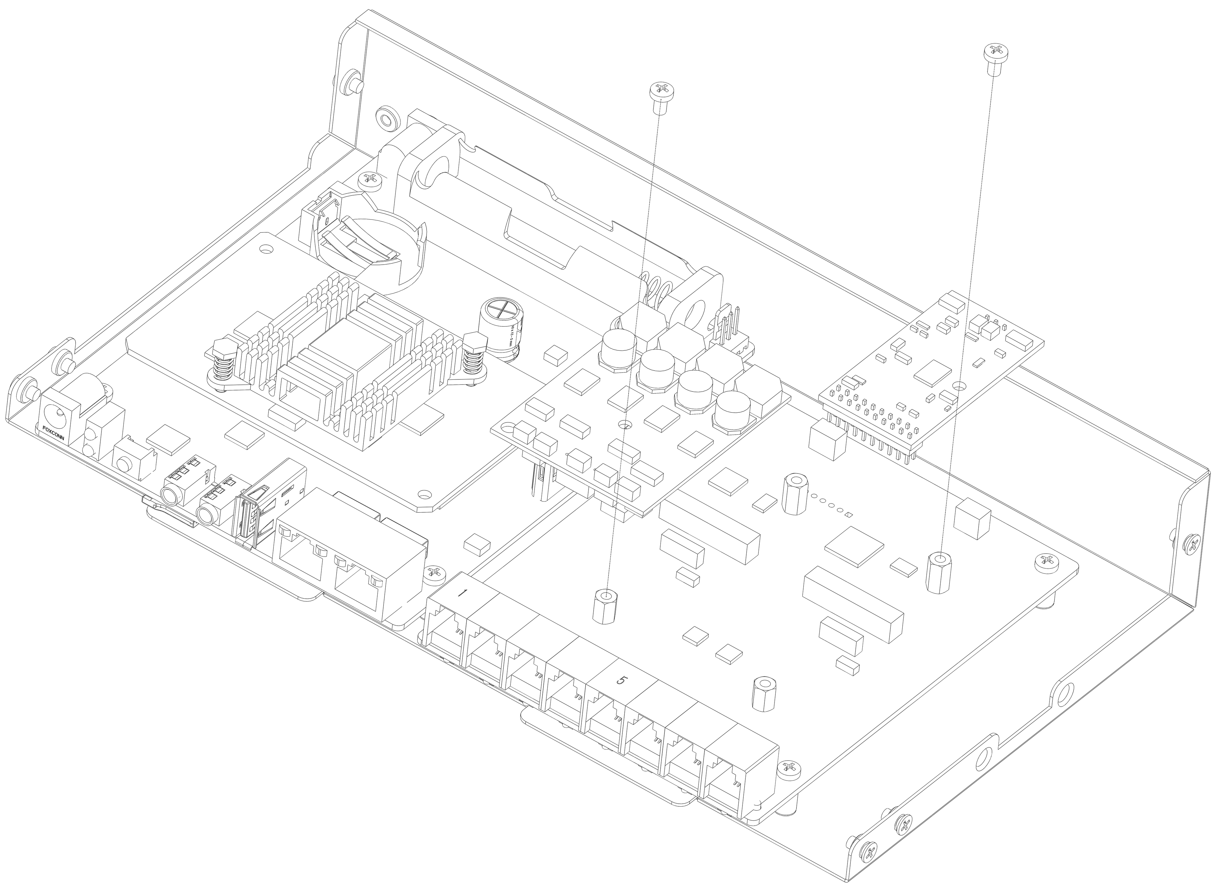
1.3.2 UC501 Series Modular Collocation
The UC501 series of products adopt modular design and are divided into new and old modules.
Below is the top view of the inside of the chassis, and the right side is the module installation area.There are four areas where you can install modules.
(1)For new module:users can choose any combination of the following three modules.
①FXS-200
②FXO-200
③FXOS-200
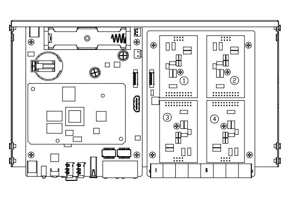
Remove the screw and install the module.
(2)For old module:The upper area is for the FXO-100/FXS-100 module and the lower area is for the FXO-400/FXS-400 module. It should be noted that the module cannot be installed on the left or right side at the same time, only supports ①+②, ③+④, ①+④, ②+③.Users can choose two module accessories to customize.
- FXO-100+FXO-100
- FXO-100+FXS-100
- FXO-100+FXO-400
- FXO-100+FXS-400
- FXS-100+FXS-100
- FXS-100+FXO-400
- FXS-100+FXS-400
- FXO-400+FXO-400
- FXO-400+FXS-400
- FXS-400+FXS-400
1.4 Specifications
Table 1-4-1 UC Series Product Specification
Item | UC300/500/501/501P |
System Capacity | Up to 800 extension registers 100 concurrent calls with G.729 codec 300 concurrent calls with G.711 codec |
Max Network Interface | 2×10/100M port |
Max FXS/FXO Interface | 8 |
USB Port | 1×USB 2.0 for external storage or disaster recovery system |
External Storage | 1×SD slot, support up to 128G |
Telephony Interface | FXS/FXO interface, Optional |
RAM | DDR3 1GB |
Storage | 16GB Onboard Flash |
Power Consumption | 16W Maximum |
1.5 Features
General
- Up to 8 FXS/FXO (PSTN/POTS) Analog Port
- Support SIP & IAX2
- Support Codecs: G.711(a-law &μ-law), G.722, OPUS, AMR-NB/WB, SILK, G723.1, G726, G729, GSM, ADPCM, iLBC, H263, H263P, H264, VP8, etc.
- Abundant HD voice codecs: OPUS, AMR-NB/WB, G.722, SILK
- Abundant HD video codecs: H261, H263, H263P, H264, VP8
- HD Video Calls
- Echo Canceller
System
- Simple and Convenient Configuration via Web GUI
- User Portal
- Extension User Privileges
- System Administrators Monitor
- Event Notification
- Support Backup/Restore
- Remote Management
- Hot Standby
- System resource monitoring
Network
- Network configuration
- Support VLAN
- Support Static Route
- Support Fail2ban
- Secure SIP calling (TLS encryption)
- Support Multiple VPN protocols including OpenVPN, L2TP, N2N, SSTP
PBX
- Import/Export Extensions
- Support SIP Forking
- Call Transfer
- Follow-Me/Ring Group/Queue
- Quickly Auto Provision IP Phones
- Support IMS VoLTE
- Flexible Inbound/Outbound Route
- Blacklist
- Support international call restrictions
- AutoCLIP
- Time Condition
- PIN List
- Automated Attendant (IVR)
- Phonebook
- LDAP Service
- Wakeup Service
- DISA (Direct Inward System Access)
- Conference
- Call Back
- Call Parking
- Paging and Intercom
- Speed Dial
- Call Recording
- Music On Hold
- Support Open API Protocol (based on Asterisk)
- Click2call
- WebPhone
- Access Control Interface based on ACL
- AI TTS
- SIP Instant Messaging
- Voicemail
- Missed Calls Notification
- Remote SMTP Email Server
- Antispam support
- Support Mail Relay
- Fax to Email
Report
- Call Detail Records (CDR)
- Billing Report
1.6 Compatible Endpoints
- Any SIP compatible IP Phone (Desktop Phones and Soft Phones for Windows, Linux, iOS and also Android platforms).
- Desktop phone examples include: OpenVox C Series, CooFone Series IP Phones provided by ZYCOO, and also Cisco, Grandstream, Yealink, Polycom, Snom, Akuvox, Escene, Favil, HTek etc.
- Soft Phone examples include 3CX, CooCall, Linphone, X-Lite, Zoiper etc.
- IAX compatible endpoints, for example, CooFone IP Phones provided by OpenVox and also Zoiper softphone.
- Analog Phones and Fax Machines
- Web Extensions (WebPhone)
1.7 Log in to the Web GUI
- Step 1
Use a CAT5 cable to connect the device to the local network where the PC is connected, or connect the device directly to the PC.
- Step 2
Dial “**89” to obtain device IP address by an analog telephone, the device defaults to a fixed IP address: 172.16.101.1
- Step 3
Make sure that the PC and the device are on the same network segment.
- Step 4
Enter the device IP address in the browser address bar (e.g. 192.168.2.218);
- Step 5
You can enter the login interface for device configuration by selecting your role and entering a password on the login interface. The default administrator username and password are admin.
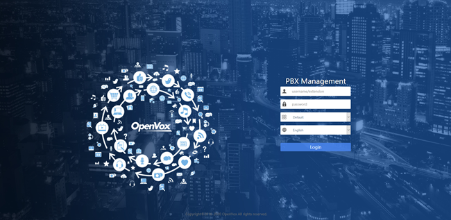
Figure 1-7-1 Login interface
1.8 Web GUI overview
The web management interface of the UC series includes three areas: System button area, Menu bar, and Configuration area.
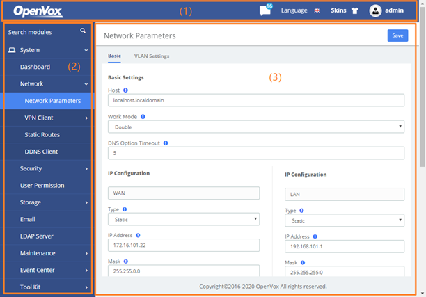
Figure 1-8-1 Web GUI layout
Table 1-8-1 Web Management Interface Layout
Item | Description |
(1) System button area | Contains buttons such as Change Password, Reboot, Logout, Skins, Language, etc., and the event notification bar, displays the current login user. |
(2) Menu bar | Displays submenus for your selection when the mouse pointer is moved onto a menu. The selection result is displayed in the configuration area. |
(3) Configuration area | View or modify configurations. |
2 System
2.1 Dashboard
The option Dashboard of menu System in UC series is a visualization tool that shows a general view of the system and gives a faster access to administrative actions in order to allow the user an easy administration of the server such as "System Resources", "Processes Status", "Hard Drives". Below a short description of each one.
System Resources: Here shows general information about the system where UC series is running. It allows to check out the history of CPU and Memory usage over the time.
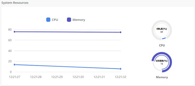
Figure 2-1-1 System Resource
Processes Status: It shows the enabled and disabled processes. Here you can start, stop and restart these processes.
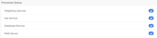
Figure 2-1-2 Processes Status
Hard Drives: Hard Drives shows the free and used space of the hard drives installed on your server.
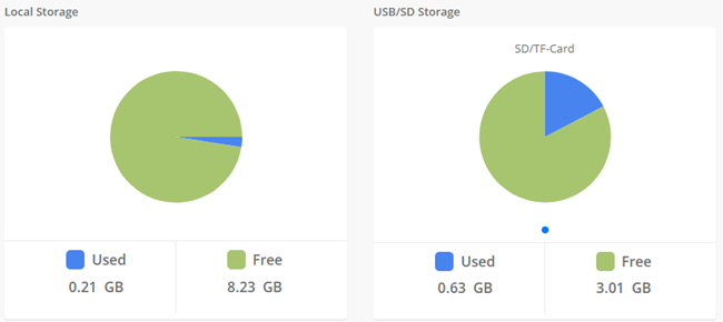
Figure 2-1-3 Hard Drives
Communication Activity: This applet shows the number of extensions, trunks and calls currently on sip server.
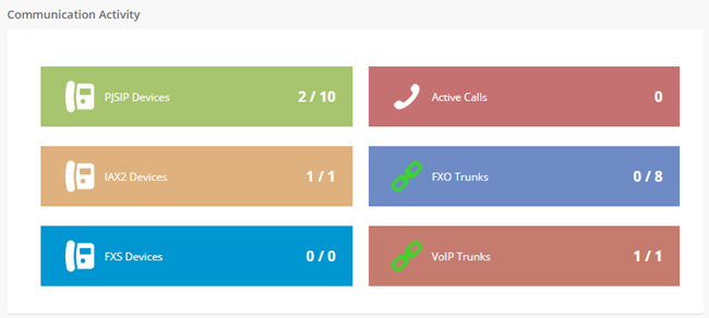
Figure 2-1-4 Communication Activity
2.2 Network
2.2.1 Network Parameters
The option Network Parameters of the Menu Network in UC series lets us view and configure the network parameters of the server.
Navigate to System > Network > Network Parameters to set network parameters according to the installed network environment.
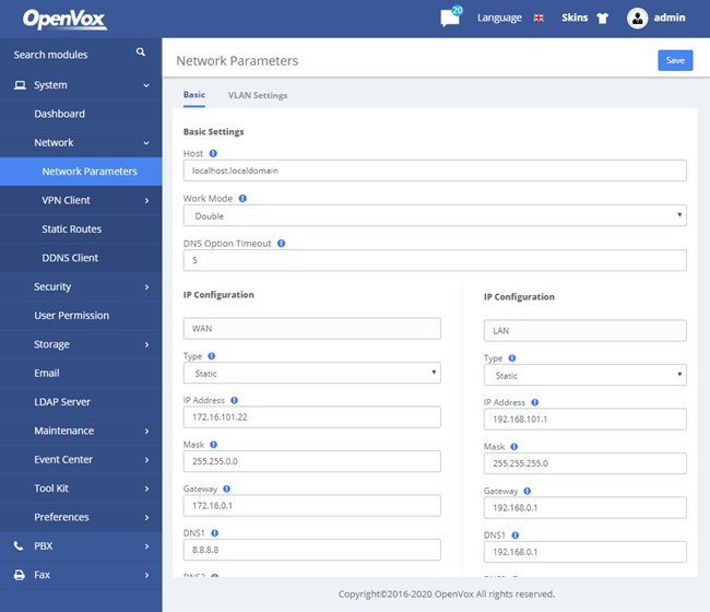
Figure 2-2-1 Network Parameters Interface
This corresponds to the general network parameters of the server.
Table 2-2-1 Description of Edit Network Parameters
Item | Description |
Basic Settings | |
Host | Server Name, for example: pbx.subdomain.com |
Work Mode | Optional work modes: Single/Double |
Gateway | IP Address of the Port of Connection (Default Gateway) |
Primary DNS | IP Address of the Primary Domain Name Server (DNS) |
Secondary DNS | IP Address of the Secondary or Alternative Domain Name Server (DNS) |
IP Configuration | |
Type | The type of IP address that the Interface has, which could be STATIC when the IP address is fixed or DHCP when the IP address is obtained automatically from a DHCP server. |
IP Address | IP Address assigned to the Interface |
Mask | The Network Mask assigned to the Interface |
MAC | Physical Address of the network Interface |
Status | Shows the physical status of the Interface, if it’s connected or not |
Default Route | Mainly used in Double work mode to determine the default exit for network traffic |
IP Address 2 | The second IP assigned to the Interface |
Mask 2 | The network mask for the second IP |
2.2.2 VPN Client
The VPN Client module of the menu Network lets us connect to the VPN Server.
Navigate to System > Network > VPN Client, chose client type and enter the Server IP Address, switching the Enable to on and save changes. Then the Server will assign this client an IP address.
The UC series offers four common VPN connections: OpenVPN, N2N, L2TP and SSTP, allowing users to establish virtual private networks, encrypt communications, and enable remote access.
OpenVPN
You can choose to directly upload the configuration package file (.ovpn format) for the connection.
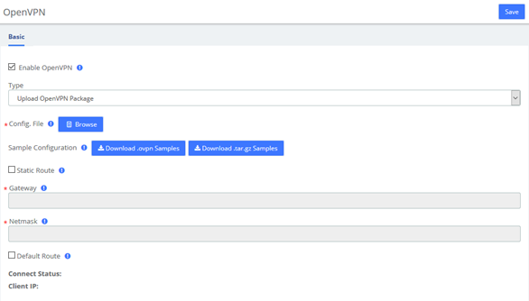
Figure 2-2-2 OpenVPN/Upload OpenVPN Package
It is also possible to manually configure the server information and upload files such as certificates to connect.
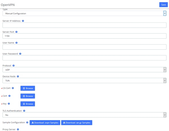
Figure 2-2-3 OpenVPN/Manual Configuration
N2N
Enter the server and user information and click the Save button to connect.

Figure 2-2-4 N2N Interface
L2TP
Enter the corresponding information and click the Save button to connect.
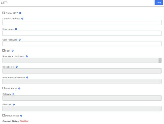
Figure 2-2-5 L2TP Interface
SSTP
Enter the corresponding information and click the Save button to connect.
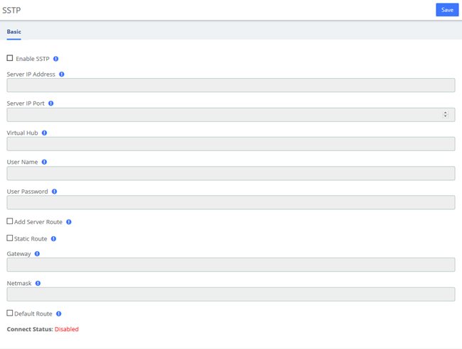
Figure 2-2-6 SSTP Interface
2.2.3 Static Routes
The Static Routes module of the menu “Network” lets users view and add the static routes.
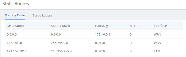
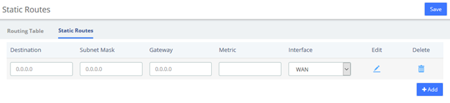
Figure 2-2-7 Static Routes Interface
Table 2-2-2 Description of Static Routes
Item | Description |
Destination | Identified the destination of IP packet. |
Subnet Mask | Identified the segment where the destination host or router locates with destination. |
Gateway | Also named Next Hop Router, defined the next hop server the packets send to. |
Metric | Used to make routing decisions, contains any number of values that help the router determine the best route among multiple routes to a destination. |
Interface | The ethernet LAN/WAN interface, defined the interface used to send packet for the specific destination. |
2.2.4 DDNS Client
Select DDNS server, enter user name, password and other information, then click Save to make DDNS take effect.
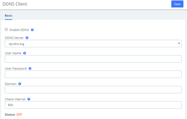
Figure 2-2-8 DDNS Client Interface
2.2.5 DHCP
DHCP Server
DHCP (Dynamic Host Configuration Protocol) is a standardized network protocol used on Internet Protocol (IP) networks for dynamically distributing network configuration parameters, such as IP addresses for interfaces and services.
With DHCP, computers/IP phones request IP addresses and networking parameters automatically from UC series WAN/LAN port which saves administrators a lot of time when compared with having to configure these settings manually.
The option "DHCP Server" allows configuring UC series’s DHCP service so it can assign IP addresses in the network.
Navigate to System > Network > DHCP Server:
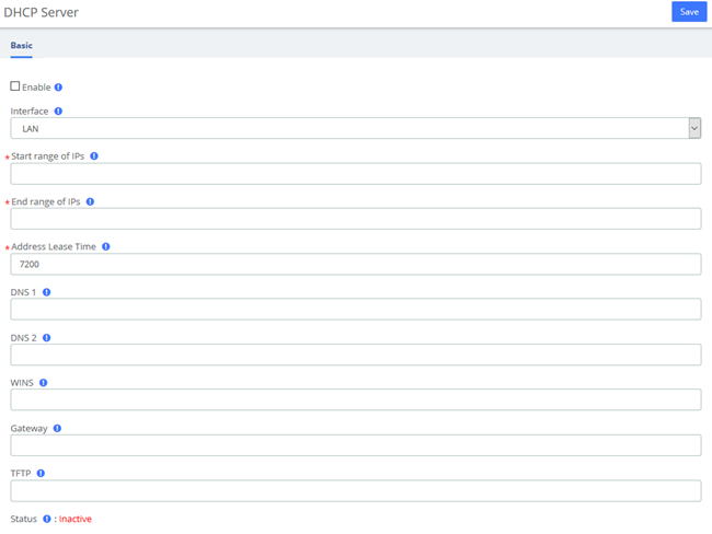
Figure 2-2-9 DHCP Server Interface
Here the description of each field.
Table 2-2-3 Description of Static Routes
Item | Description |
Enable | It indicates if the DHCP service is enabled or disabled |
Interface | Specify the start IP of the port (Network interface configuration must be static). |
Start range of IPs | This will be the beginning of the IP range that the server will provide. |
End ranges of IPs | This will be the ending of the IP range that the server will provide. |
Address Lease time | Duration for DHCP server to lease an address to a new device. When the lease expires, the DHCP server might assign the IP address to a different device. Default value is 7200 seconds. |
DNS 1 | This address is the Primary DNS that the server will provide. |
DNS 2 | This address is the Secondary DNS that the server will provide. |
WINS | It is the IP of the WINS Server that will be given to Windows machines. |
Gateway | This is the address the server will provide as Gateway. |
TFTP | Enter the TFTP server address if required which may be used to auto provision your IP phones. |
Status | Display current DHCP status. |
To save changes just click on the button Save.
DHCP Client
This module shows a list of DHCP clients and their status info.
Navigate to System > Network > DHCP Client and you will see a list of all devices receiving their IP address from the UC series system.
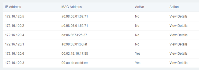
Figure 2-2-10 DHCP Client Interface
To see the leased time of each address, click on View Details.
Assign IP to Host
With this option you can assign an IP address to a specific device through MAC address. When the device requests an IP address, the DHCP server will provide it according to the MAC address. All the associations created by the user are shown in a list.
Navigate to System > Network > Assign IP Address to Host.

Figure 2-2-11 Assign IP Address to Host
To create a new association, click Add button. Fill out the required information and click on Save button.
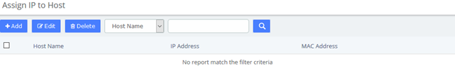
Figure 2-2-12 Add Assign IP Address
The following table shows the description of each field:
Table 2-2-4 Description of Assign IP Address
Item | Description |
Host Name | Name that you want to assign to the device |
IP Address | IP Address you want to use for the device |
MAC Address | MAC number of the device |
2.3 Security
2.3.1 Audit
The module Audit of the menu Security in UC series shows a list of all the users that have logged in the system with the date, the username, the source IP address and other details. The results can be filtered by date and string. The coincidences with the string will be highlighted in the results.
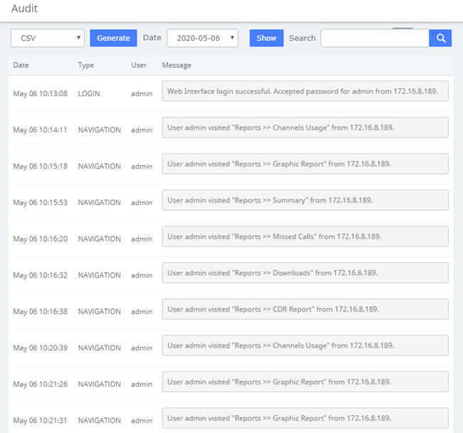
Figure 2-3-1 Audit interface
The results of the search can be downloaded in different formats such as PDF, XML and CSV by clicking on the Generate button.
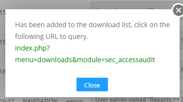
Figure 2-3-2 Generate Audit Content
By clicking on the URL above, you can jump to the Reports > Downloads page. Click the Download button to download the generated file.
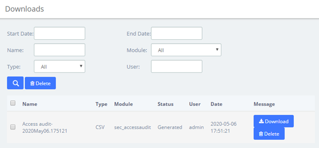
Figure 2-3-3 Download Audit Content
2.3.2 Weak Keys
The module Weak Keys of the menu Security lets us identify the keys that are not enough strength for the extensions created in the UC series (SIP and IAX2). This module shows all the extensions but you can filter the results by entering a specific extension number or part of it.
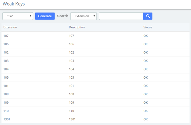
Figure 2-3-4 Weak keys interface
You can generate the results in different formats such as PDF, XML and CSV by clicking on the Generate button.
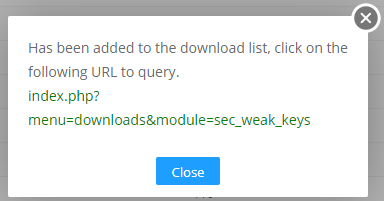
Figure 2-3-5 Generate Weak Keys Content
By clicking on the URL above, you can jump to the Reports > Downloads page. Click the Download button to download the corresponding file.

Figure 2-3-6 Download Weak Keys Content
Change Key
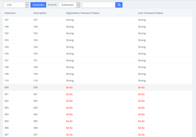
Figure 2-3-7 Change Weak Keys
If the extension's registration/user password is not strong enough, you will be prompted in the status bar and you can change the key by click the red prompt So-So. After clicking this link, you will jump to the extension setting page where you can set a new password. The password is at least 8 characters long and must contain at least 1 digit number, at least 1 uppercase letter and at least 1 lowercase letter. After setting the new secret, click the Save button to apply the changes.
2.3.3 Certifications
The Certifications module of the Security menu greatly enhances the security of the device. The UC series supports TLS encrypted calling (SIP), which requires SIP phone support.
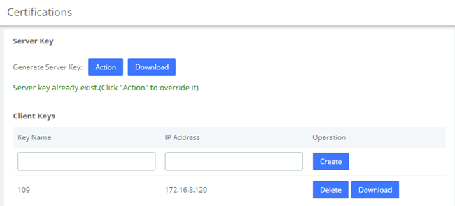
Figure 2-3-8 Certifications interface
Clicking Action to generates the Server Key, which will overwrite the original certificate if it already exists. Click Download to download the Server Key (including the asterisk.pem and ca.crt files).
Note: After regenerating the Server Key, the original Client Keys will be invalid and will need to be recreated in the Client Key.
Enter the Key Name and IP Address in the Client Key to Create the certificate.
Note that if the device changes its IP, the corresponding client key will need to be generated again.
Download the Client Key (including [Key Name].pem and ca.crt), please import the Client Key into your SIP phone for encrypted transmission using TLS.
After mutual authentication between the client and the server, the phone can make encrypted calls. The specific parameters of the Certification module can be set in the column of Transports > TLS under PBX>Settings>SIP Settings.
2.3.4 Hot Standby
Hot Standby is a highly reliable application of software and hardware combination. The Hot Standby system consists of two identical UC devices and control software system. The two devices appear as a single system in the network, and externally as an independent network IP, and control and management in the mode of a single system. The system mirrors the data and operational status of the two devices (including hard disk data and memory data), enables hot backup between the master and slave devices and seamless switching. Thus, providing stable and reliable services for users and achieving the high availability solution of dual-unit systems.
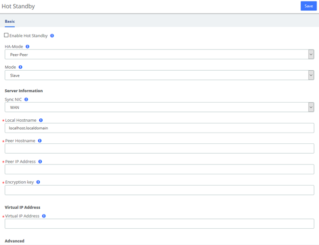
Figure 2-3-9 Hot Standby interface
Table 2-3-1 Description of Hot Standby Parameters
Options | Description |
HA-Mode | Peer-Peer hot standby mode |
Mode | The default is slave mode. The device that turns on the hot standby firstly is the master server. |
Sync NIC | The network adapter which is used to heartbeat and synchronous data. |
Local Hostname | Hostname of the local host |
Peer Hostname | Hostname of the peer host |
Peer IP Address | IP address of the peer host |
Encryption key | A phrase or password to use for encryption. It has to match on both nodes. |
Virtual IP Address | Enter an unused IP address. The extensions would communicate with the server via the virtual IP address. The two PBX in the hot standby mode should configure the same Virtual IP address. |
Advert Time | It sets the interval at which Heartbeat keep-alive packets are sent. The default is 2s, the default dead time is 3 * advert time. |
2.3.5 Firewall
Firewall Rules
UC series system has been preconfigured with a built-in firewall that protects your IP phone system from unauthorized access, phone calls and other attacks. It allows building Firewall rules to control the packets that send and receive by the UC devices. To manage the firewall, navigate to web menu Security->Firewall.
The firewall is off by default and has seven built-in default rules: accept all internal traffic, block all traffic from outside, and block all ports. After checking the Enable Firewall, click the Save button and the firewall will be turned on. If you don't want to be pinged by another device, you can check the Disable Ping.
Once the firewall is enabled, you can create, delete, modify, disable and reorder firewall rules. Click the Save button after each operation or it will be invalid in the system. Click the Save button every time a new or edited rule is completed, and then the list will automatically display your changes, otherwise they are invalid in the system.
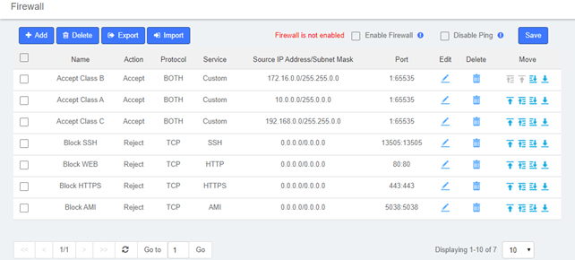
Figure 2-3-10 Firewall Rules
Adding a New Rule
Click add to fill out the form to create a new firewall rule. The form will vary depending on the parameter selected for Service. You can simply select the Action and Service type, or customize the Service and set the port range.
In the Source IP Address/Subnet Mask field, you must enter an IP address in the format x.x.x.x/y, where y is the subnet mask and should be a number between 0 and 32. If you enter the default IP address (0.0.0.0), the subnet mask will be 0.
Once the rule is created, click the Save button and the new rule will appear in the list. Be sure to save the changes, otherwise, they will not take effect in the system.
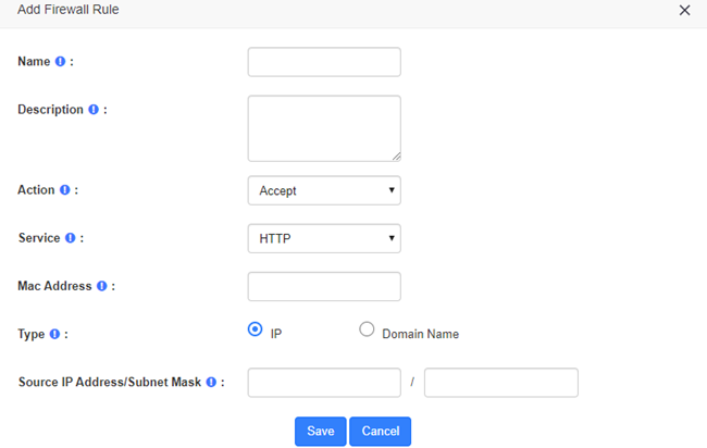
Figure 2-3-11 Add a new rules interface
Table 2-3-2 Description of Firewall Rule Parameters
Options | Description |
Name | Give this rule a descriptive name to help you identify it. |
Description | A brief description of this rule. For example: accept a specific host to access the web interface for configuration. |
Action | Accept: The device will accept access to the specified address. Deny: The PBX will deny the connection from the specified address and will send an error message to the other side informing them that the device has denied the connection. Ignore: The device will ignore the connection from the specified address, drop the data directly, and do not give any feedback. To improve the security of your IPPBX system, you can use Ignore actions to avoid malicious attacks to detect the server information of your device. |
Service | Optional or customizable system services are available. By selecting a service, the default port for that service is selected. Of course, you can also customize the firewall service by selecting "Custom" and filling in the "Protocol" and "Port" options. |
MAC Address | The MAC address format is: XX:XX:XX:XX:XX:XX:XX:XX:XX:XX. |
Type | Select the type that matches this rule, either an IP address or a domain name. |
Source IP Address/ Subnet Mask | The IP address format is: IP address/subnet mask, subnet mask needs to be written in full format, the short format is not supported. For example, 192.168.5.100/255.255.255.255 means that the rule applies to 192.168.5.100; 192.168.5.0/255.255.255.255.0 means that the rule applies to IP between 192.168.5.0 and 192.168.5.255. |
Domain Name | Appears when "Domain Name" is selected for Type. The firewall rules will match the domain name filled in here. |
Protocol | Appears when the service is selected "Custom", selects the protocol that applies to this rule, selects UDP, TCP and BOTH (UDP and TCP) |
Port | Appears when the service selects "Custom" to specify the ports for this rule, which can specify port groups and individual ports. When specifying a port group, the left side is the start port and the right side is the end port (included), e.g. "5060:5070" means to specify ports 5060 to 5070 (including 5070). When specifying a single port, just fill in the same port number on the left as on the right. For example, "5060:5060" means that port 5060 is specified. |
Editing a Rule
To edit an existing rule, click on the  icon corresponding to the rule. Here you can modify parameters of the rule.
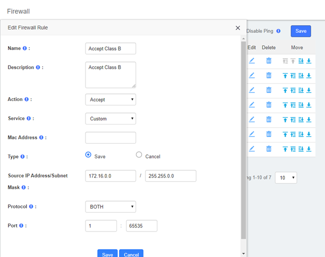
Figure 2-3-12 Edit Firewall rules interface
Deleting a Rule
To delete a rule, just select the corresponding checkbox and click on the Delete button. Be sure to save the changes or they will not work in the system.
Reordering the Rules
You can modify the order of the rules by clicking on the blue arrows in the column Move. If you click on the  button of a rule, this rule will go up one position and if you click on the
  button, it will go down one position. If you click on the
  arrow, the rule will rise to the highest position which is the highest priority. Similarly, the
  arrows move the rule to the lowest position. Make sure you save the changes, so they will take effect in the system after modifying the position of the rules.
Export rules
Firewall rules now support exporting CSV files, just click the Export button and the browser will automatically download the exported CSV file. Note that please allow browser pop-ups.
Import rules
The firewall now supports importing CSV files to create rules in bulk, click the Import button and a popup will appear as follows
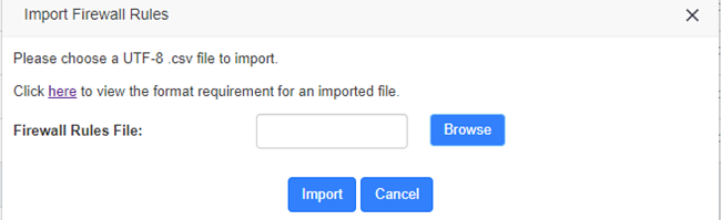
Figure 2-3-13 Import Firewall Rules interface
Click Browse to select the edited CSV file, then click Import to successfully import. The importation instructions are as follows.
Table 2-3-3 Import Parameters - Firewall Rules
Parameter | Importance | Restriction | Default Value |
Name | Required | · The following characters are NOT allowed: & " ' \ < > ` | · The maximum length is 127. | N/A |
Description | Optional system services and custom services | · The following characters are NOT allowed: & " ' \ < > ` | · The maximum length is 511. | N/A |
Service | Optional system services and custom services | Permitted value: HTTP HTTPS SSH AMI SIP-UDP SIP-TCP SIP-TCP SIP-TLS SIP-RTP WEBRTC IAX2 LDAP MYSQL Custom | Custom |
Action | Required | Permitted value: Accept Reject Drop | Accept |
Protocol | Required | Permitted value: udp tcp both | udp |
MAC Address | Optional system services and custom services | MAC address format required. | N/A |
Type | Required | Permitted value: IP Domain | IP |
Source IP Address/Subnet Mask | Required if Type is IP | IP format required. | N/A |
Domain | Required if Type is domain | Domain format required. | N/A |
Port | Required | The valid port range is 0-65535. | N/A |
After clicking the link and opening Import Parameters - Firewall Rules page, click Example and the browser will automatically download the template of the CSV file.
2.3.6 Fail2Ban
Fail2ban scans log files (e.g. /var/log/apache/error_log) and ban IPs that show the malicious signs -- too many password failures, seeking for exploits, etc. Generally, Fail2Ban is then used to update firewall rules to reject the IP addresses for a specified amount of time, although any arbitrary other action (e.g. sending an email) could also be configured. Out of the box, Fail2Ban comes with filters for various services (apache, courier, ssh, etc).
Fail2Ban is able to reduce the rate of incorrect authentications attempts however it cannot eliminate the risk that weak authentication presents. Configure services to use only two factors or public/private authentication mechanisms if you really want to protect services.
The module "Fail2Ban" allows configuring Fail2ban service so it can prevent the UC series from malicious attacks. Navigate to System > Security > Fail2Ban to configure rules.
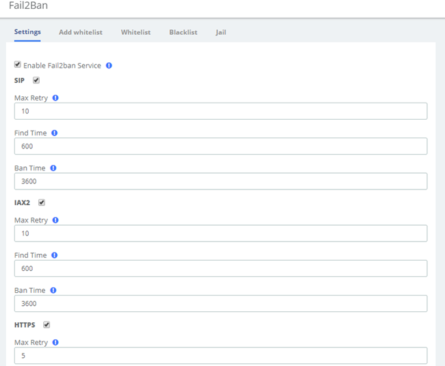
Figure 2-3-14 Fail2Ban interface
Max Retry limits the authentication attempts. Find Time defines the time duration from the first attempt to the last attempt which reaches the “Max Retry” limitation. Ban Time is the time in seconds the IPPBX system will block the IP which exceeds max retry. Ban Time don’t take effect on any whitelisted addresses.
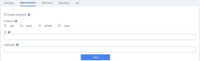
Figure 2-3-15 Fail2Ban add whitelist
Add whitelist allows you to add a trusted IP addresses or network addresses to the system IP whitelist. The IPs in the whitelist will always be treated as trusted IP’s and will not be filtered by the firewall rules.
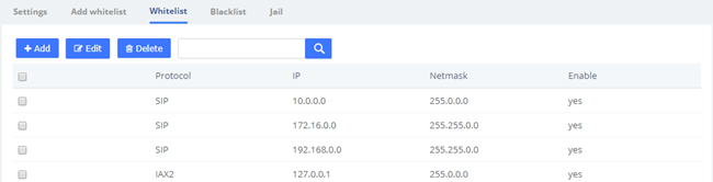
Figure 2-3-16 Fail2Ban whitelist
If mistakenly disabled, you can log in to that device with another IP and enter the blacklist to unblock it.

Figure 2-3-17 Fail2Ban blacklist
Jail is generally used for permanent bans, or "top bans", which are disabled by default. When running Fail2Ban Jail, if an IP has already been banned, and the IP continue to try to access and reach Max Retry within the set Find Time, then it will be blocked for longer time, this time is set by Ban Time, if Ban Time is set to -1, then it means permanent blocking.
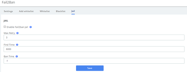
Figure 2-3-18 Fail2Ban Jail
2.4 User Permission
System > Users Permission allow the creation and modification of permissions for users accessing the web interface. An extension that has been granted access can log into the system using the SIP extension number/login password. It should be noted that by default, the user permissions give the Me module permissions for all extensions to log in and use some simple features.
Click the Create button to grant permission to the specified extension, then Click Apply to save the configuration.
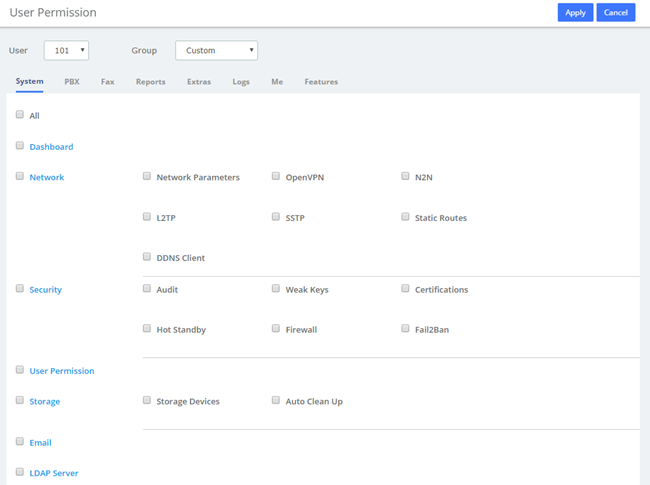
Figure 2-4-1 Create New User
In the User drop-down box, you can select the corresponding extension, and in the Group drop-down box, you can select Custom/Administrator. If you set the user group as Custom, you can check the desired function module to give the user web privileges; if you select the user group as Administrator, all function privileges are enabled by default. Note that if some permissions are unchecked at this point, they will automatically become the Custom group after saving, in other words, the Administrators group will have all permissions at all times.
In addition to Features and Me modules, the other permissions correspond to the function menu on the left side of the page.
Me Bar provides basic permissions after extension user login and does not recommend modifications. See 8 Me Bar for details.
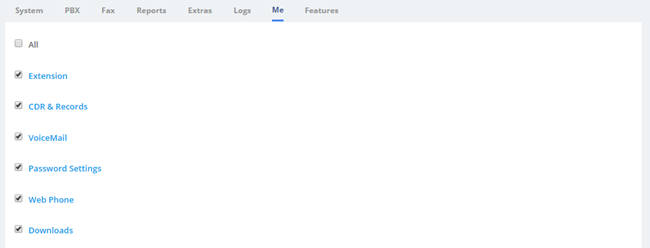
Figure 2-4-2 User Permission/Me
The Feature provides enablement of some features associated with the extensions that are also used in the Me Bar.
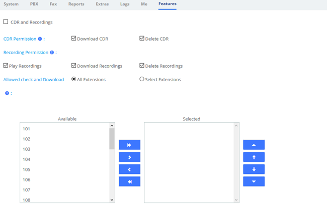
Figure 2-4-3 User Permission/Features
Table 2-4-1 User Permission/Features
Type | Option | Description | |
CDR Permission | Download CDR | Allow the extension to download the CDR associated with this extension in the Me module | |
Delete CDR | Allows the extension to delete the CDR associated with this extension in the Me module | ||
Recording Permission | Play Recordings | Allows extensions to play recordings in the Me module | |
Download Recordings | Allows extensions to download recordings in the Me module | ||
Delete Recordings | Allow extensions to delete recordings in the Me module | ||
Allowed check and Download | Allows extensions to view downloads from other extensions in the "Downloads" section of the Me Bar | ||
2.5 Storage
2.5.1 Storage Devices
In this module, users can format or mount external storage devices such as TF/SD cards plugged into UC devices, or add network storage. It should be noted that the system only allows one external device to be set as the primary storage device, which means that when one external storage device is mounted, other devices cannot be mounted at the same time. The large files such as audio files generated by the system will be automatically stored in the mounted external device.
Click System>Storage>Storage Device.
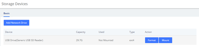
Figure 2-5-1 Storage Devices Interface
Click Format to format the inserted device. For TF/SD/U disk devices, only EXT4 or FAT file systems can be mounted. For non-EXT4/FAT file systems, please format them.
Click Mount to mount the device that has been inserted. At that time, large files such as recordings generated by the system will be automatically stored on the device. The Add Network Drive button will change to gray, and the Unmount button will appear.
Click Unmount to unmount the mounted device. Add Network Dive at that time will return to normal and click is valid.
Click Add Network Drive to add network storage, as shown in the following figure.
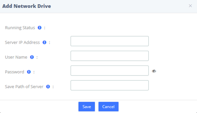
Figure 2-5-2 Add Network Drive
Currently network storage only supports CIFS services. Enter the Network Drive information, click Save, and you can mount it successfully.
2.5.2 Auto Clean Up
The option Auto Clean Up of the menu Storage allows you to configure the clean-up frequency.
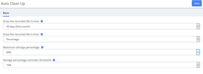
Figure 2-5-3 Auto Clean Up Interface
2.6 Email
The Email is mainly used in conjunction with Event Center, and by setting the remote SMTP configuration parameters of the mailbox, you can enable the Email service, send event reminder email and fax email, and provide you with timely and accurate information. It can also be combined with Voicemail to Email, allowing you to check your voice messages anytime, anywhere.
Note that there is no built-in SMTP server in the UC system, but an external SMTP server is used.
The fields for configuring Email are shown below.
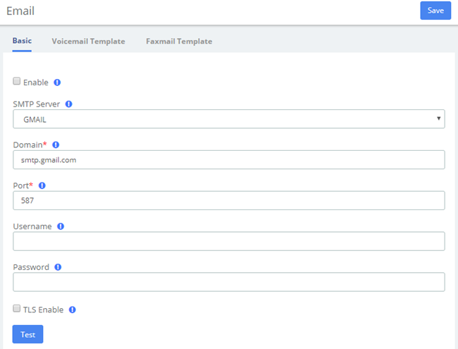
Figure 2-6-1 Email/Basic
Table 2-6-1 Definition of Email
Item | Definition |
Enable | Decide whether to turn on SMTP service |
SMTP Server | SMTP server type. Multiple server types are built in, associated with Domain, or can be customized by selecting "other" |
Domain | SMTP server address. It is automatically filled according to the SMTP server. When the SMTP Server selects "other", it needs to be filled manually. |
Port | Port to establish the connection with SMTP Server. Common ports are 25, 465 (SSL), 587 (SSL) |
Username | Username of email account from SMTP Server. |
Password | Password of email account from SMTP Server |
TLS Enable | To enable certificates of TLS (Transport Layer Security). Generally, this check is required when using ports that require SSL encryption, such as 465/587. If checked when using a port that does not require encryption, it will cause the send to fail |
After setting Email, if you want to send a test email to check whether the Email function is enabled correctly, please click Save and then click Test, and a dialog box will pop up for sending.
The Voicemail Template and Faxmail Template options edit the Voicemail and Faxmail Template. After filling in the template variables in the Subject or Content according to the example shown above, they will be replaced with the corresponding parameter values when the actual email is sent.
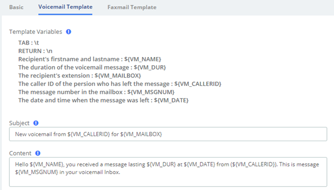
Figure 2-6-2 Email/Voicemail Template
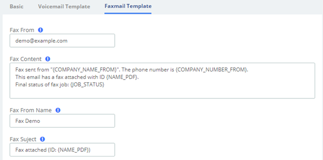
Figure 2-6-3 Email/Faxmail Template
2.7 LDAP Server
LDAP (Lightweight Directory Access Protocol) is a protocol for accessing directory services. It is generally used as a phone book on IPPBX. Based on the available LDAP services, it meets the requirements for fast search of phone directories. You can set up UC IPPBX as a server.
If you want to use LDAP service, just check the Enable LDAP service saving checkbox, and use the default configuration for the rest of the content. Once LDAP is set up, you can search the LDAP directory and find contacts on your IP phone.
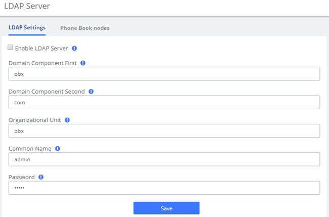
Figure 2-7-1 LDAP Settings
The UC has a built-in default phonebook node that contains all extensions on the system, which cannot be deleted or edited.
Of course, you can also manually add a phone book node, click the Add button, enter the phone book name and save. Click Edit to add your contact information.
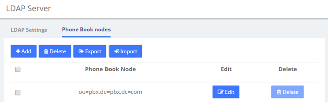
Figure 2-7-2 Phone Book Nodes
2.8 Maintenance
2.8.1 Firmware Update
The option Firmware Update of the menu Maintenance allows you to update the firmware version by uploading firmware file you download from the official website as well as update firmware online. Note that online upgrades are not recommended if the network is in poor condition.
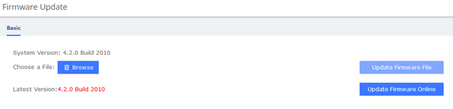
Figure 2-8-1 Firmware Update
2.8.2 Cloud Management
The UC series has full support for the OpenVox cloud management platform.
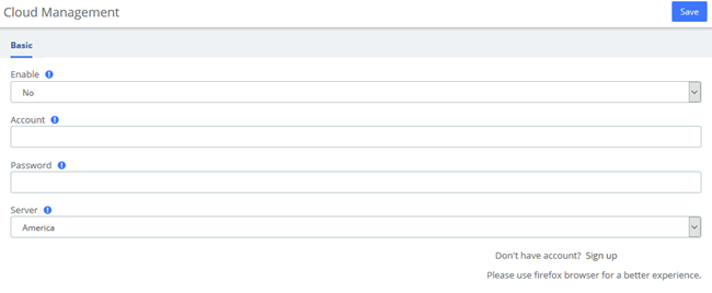
Figure 2-8-2 Firmware Update
After the device is connected to the Cloud Management Platform, users can access the gateway's WEB page or SSH access to the background through the Cloud Management. In addition, it can monitor whether the device is connected to the Cloud Management, provide functions such as password reset, online upgrade, reboot, etc., The Cloud Management Platform can also count your device model, number, distribution area, monitor your account activity and so on, providing you with efficient and excellent service and experience.
Table 2-8-1 OpenVox Cloud Management Platform
Options | Definition |
Enable | Yes/No. Indicates that the cloud management function is enable/disable |
Account | An account or email registered on the cloud management platform. |
Password | Password for the account registered on the cloud management platform. |
Server | Three servers are currently supported, including American, China and Europe. |
Connect Status | Whether or not you are currently connected to a cloud management platform. |
2.8.3 Backup & Restore
The Backup & Restore option in the System menu allows you to back up and restore the configuration of the UC system.
If you have already made a backup before that, you can click Browse to select your backup file, upload it and select Restore to restore the backup. When you restore a backup, you will be asked if you want to keep the IP address of your current system. If you choose no, the IP address of your system will be changed to the IP address of your backup after restoration. You can also click Reset to restore the factory defaults.
Please note that both the restore backup and reset operations are not reversible.
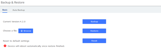
Figure 2-8-3 Backup & Restore/Basic
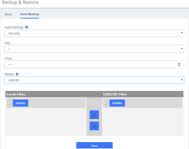
Figure 2-8-4 Backup & Restore/Auto Backup
To enable Auto Backup, navigate to System > Maintenance > Backup & Restore > Auto Backup, change the disable option to the frequency you want. There are three media you could select to back up your config file: USB/SD Card, FTP and CIFS.
2.8.4 Login Settings
Navigate to System > Maintenance > Login Settings to setup the login mode and port.
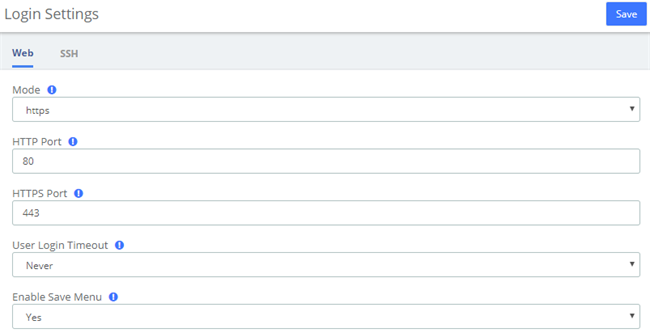
Figure 2-8-5 Login Settings Interface
The SSH settings page requires Developer Mode to be enabled, see 2.11.5.
After you turn on Developer Mode, you can log in and set up SSH. SSH default port is 13505, select Enabled-On option, set Name and P. Click Save.
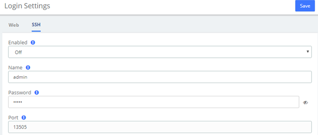
Figure 2-8-6 SSH Settings interface
2.8.5 Reboot Settings
UC system supports setting timed automatic restart. Navigate to System > Maintenance > Reboot Settings.
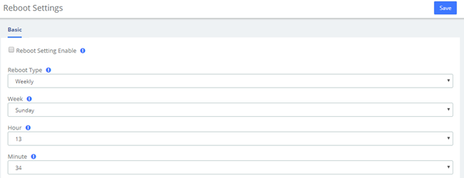
Figure 2-8-7 Reboot Settings Interface
If you want to reboot your system directly, you can click on admin>Reboot in the upper right corner:
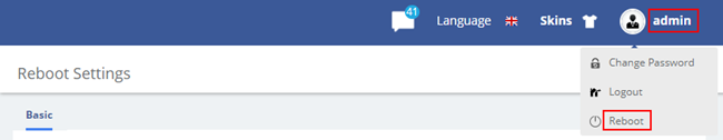
Figure 2-8-8 Reboot
2.9 Event Center
UC system provides event monitoring and alert function, users can set events that need to be monitored and notification content, after adding notification contacts, the device will send reminders by sending emails or calling extensions, so that users can fully grasp the system dynamics.
2.9.1 Event Settings
When the Record column checkbox is checked, the system will record the corresponding event in the Event Logs, or you can click the  at the top to view it; when the checkbox of the Notification column is checked, you can set the notification by email or phone, but you need to add the contact information in advance.
Click Edit to edit the Notification Template and personalize the notification.
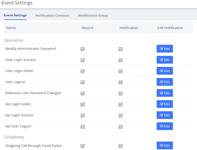
Figure 2-9-1 Event Settings
You can set up Notification Contacts to be notified by sending an email or calling when an event occurs. Click to Add contacts
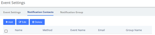
Figure 2-9-2 Notification Contacts
Once you are done, click Edit to edit the current contact and Delete to delete the contact. Of course, it is also possible to select multiple contacts for bulk deletion.
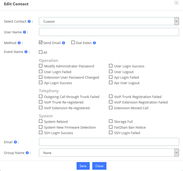
Figure 2-9-3 Edit Contact
Also, you can add a Group for Notification.
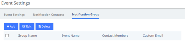
Figure 2-9-4 Notification Group
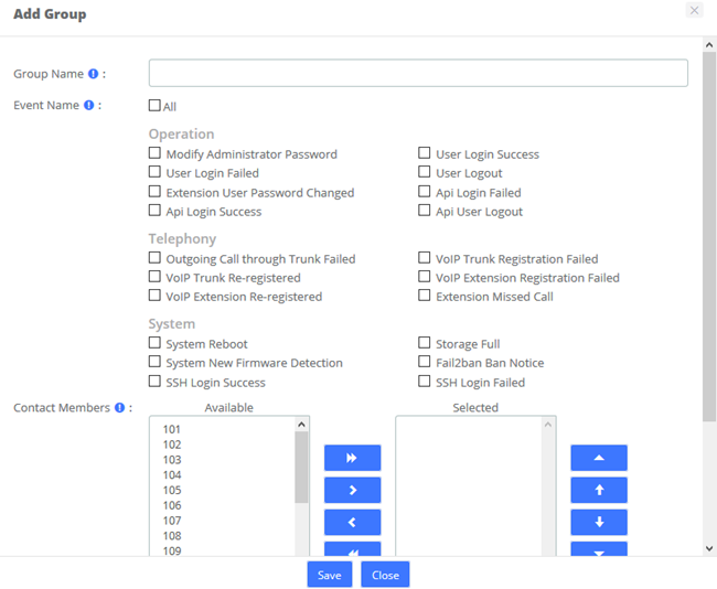
Figure 2-9-5 Edit Group
2.9.2 Event Logs
You can view logs related to monitored events in both the notification bar in the upper right corner and the Event Center > Event Logs page.
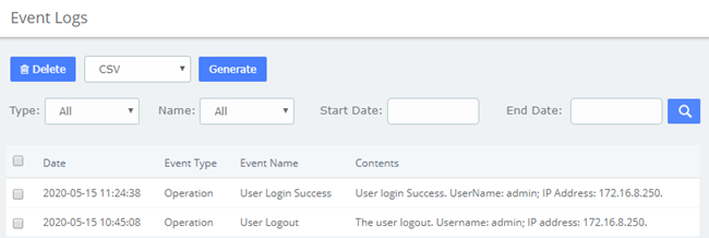
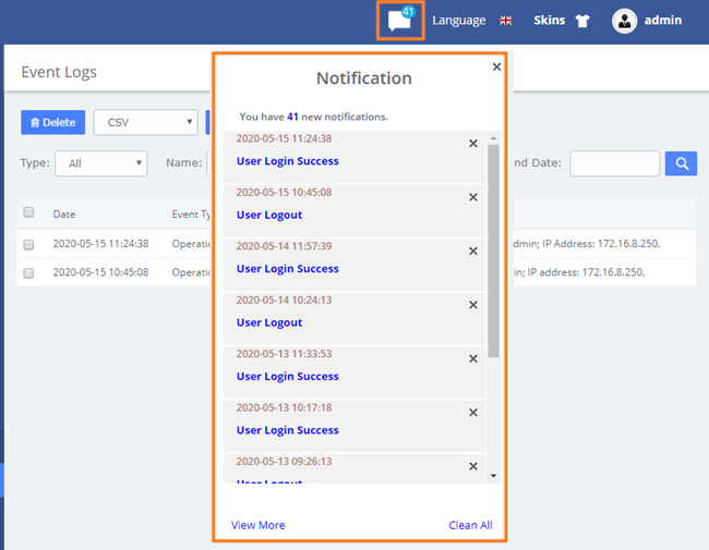
Figure 2-9-6 Event Logs
2.10 Tool Kit
2.10.1 Network Capture
The UC series provides network packet capture function for ease of user to analysis, capture and monitor the network status, RTP streams, protocol and so on.
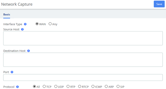
Figure 2-10-1 Capture interface
2.10.2 Port Monitor
It also provides Port Monitor module for user to monitor and record the port communications.
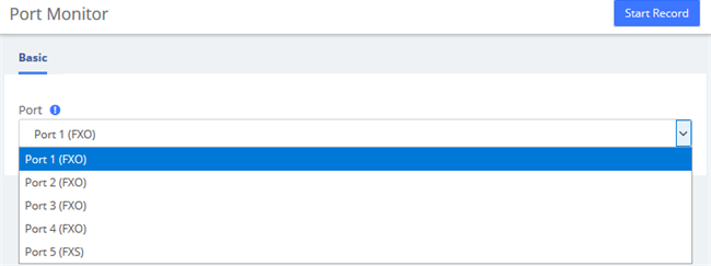
Figure 2-10-2 Port Monitor interface
2.10.3 IP Ping and Traceroute
The IP Ping and Traceroute module assist user to check the network connectivity.
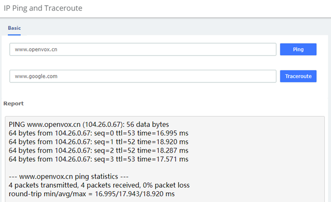
Figure 2-10-3 IP Ping and Traceroute interface
2.11 Preference
2.11.1 Language
Under the Language module in the Preferences menu, you can change the language of the UC system web interface. Select your desired language from the language list and click Save.
You can also download or upload languages you need.
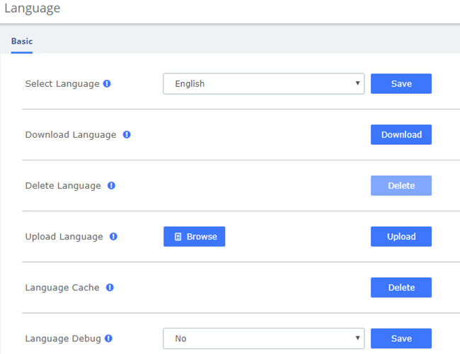
Figure 2-11-1 Language setting
At the same time, the UC system supports uploading language packs. You can click Download to download the current language pack, modify the language pack file based on it, then Upload and use the new language pack. Note that the language package is cached by default to ensure system smoothness. When debugging a new language package, you can click Delete Language Cache, then select Language Debug Yes and save.
2.11.2 Date/Time
The option Date/Time of the Menu Preferences in UC series lets us configure the Date, Hour and Timezone for the UC series Web Interface. Select the new date, hour and timezone and click on the Apply changes button.
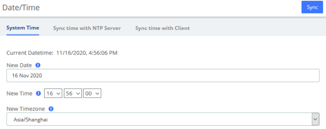
Figure 2-11-2 Date/Time Interface
Alternatively, system time can be synchronized automatically with the NTP server/local client.
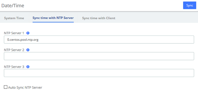
Figure 2-11-3 Sync time with NTP Server
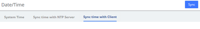
Figure 2-11-4 Sync time with Client
2.11.3 Currency
Currency module of menu Preferences allows us change the currency for Reports in UC series.
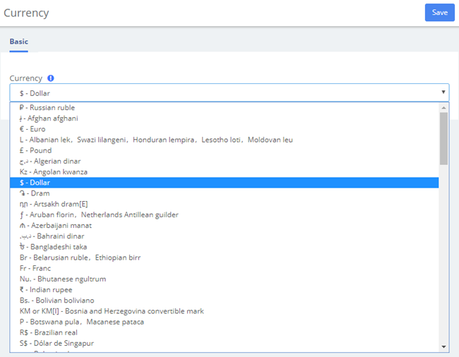
Figure 2-11-5 Currency Setting interface
Select a currency from the available options and click on the Save button.
2.11.4 About
Navigate to System >About, some basic information about the UC System is displayed, you can see the hardware version, model name, etc.
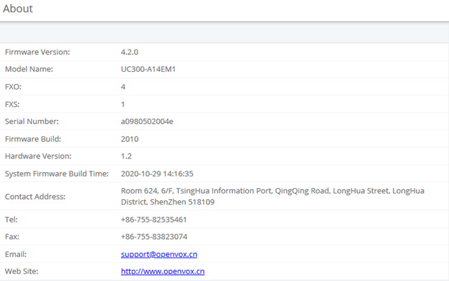
Figure 2-11-6 About information
2.11.5 Develop Mode
Under About module, five consecutive clicks on the Hardware Version will bring up a dialog prompt, check it and save it to enter developer mode.
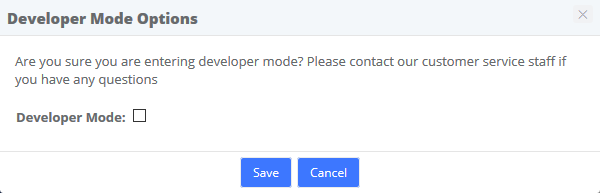
Figure 2-11-7 Developer Mode
3 PBX
The Menu PBX lets us configure extensions, trunks, routes, dialplan, queues, IVR and so on for UC series.
In this menu, we can observe that we have different options for configuration.
3.1 Extensions
3.1.1 Extensions
The Extensions Module is used to set up each extension on your system. In the Extensions module, you will set up the extension number, the name of the extension, the password, voicemail settings for the extension, and other options.
Normally, each physical phone will be assigned to one extension. If you have a phone that has more than one "line" button, you would normally make each line button register to the same extension number, and then use the line buttons to manage multiple calls to and from the same line. However, you could also create two or more extensions and assign each extension to a different line button.
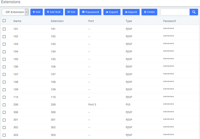
Figure 3-1-1 Add an Extension interface
Click one of extensions number and edit it:
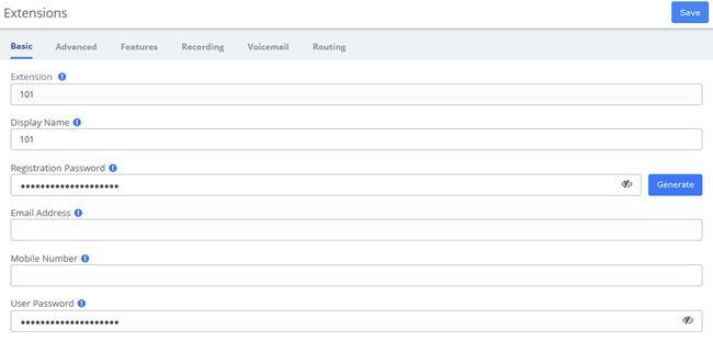
Figure 3-1-2 Extension parameter interface
Table 3-1-1 Definition of Extension parameter
Item | Description |
Basic | |
User Extension | The extension number to dial to reach this user. |
Display Name | The CallerID name for calls from this user will be set to this name. only enter the name, NOT the number. |
Registration Password | Password configured for the extension to register. |
Email Address | The email can be used to email notification to the extension user. |
Mobile Number | The extension contacts phone number. |
User Password | Password configured for the extension to login web. |
Advanced | |
Account Code | Account code for the device |
Max Contacts | Maximum number of endpoints that can associate with this device |
Web Phone | Enable web phone will let user make and receive calls without installing any plugin in web browser. |
Dtmfmode | The DTMF signaling mode used by this device, usually rfc2833 for most phone. |
Audio Codecs | Codecs supported by the device, you can choose the codecs which you want. |
Video Codecs | Video codecs supported by the device |
Ring Timeout | Select the time in seconds. |
Transport | This sets the allowed transport settings for this device and the default (Primary) transport for outgoing. The default transport is only used for outbound message until a registration takes place. During the peer registration the transport type may change to another supported type if the peer requests so. In most common cases, this does not have to be changed as most devices register in conjunction with the host=dynamic setting. If you are using TCP and/or TLS you need to make sure the general SIP Settings are configured for the system to operate in those modes and for TLS, proper certificates have been generated and configured. If you are using websockets (such as WebRTC) then you must select an option that includes WS. |
User Agent | When registering, SIP phones will be sending packets containing the user agent string. If the prefix of the user agent does not match the value defined here, the registration will fail. |
Permitted IP/Subnet Mask | Permitted IP/Subnet Mask |
Dictation Service | Allow the device to support dictation service. |
Dictation Format | The format of dictation. |
Language Code | Choose a different language for the user if he/she is not a native speaker than default system voice prompts. |
CID Num Alias | The CID Number to use for internal calls, if different from the extension number. This is used to masquerade as a different user. |
SIP Alias | If you want to support direct sip dialing of users internally or through anonymous sip calls, you can supply a friendly name that can be used in addition to the users extension to call them. |
Features | |
Outbound CID | Override the callerid when dialing out a trunk. Any setting here will override the common outbound callerid set in the trunk admin. Format: “caller name” <#######> Leave this filed blank to disable the outbound callerid feature for this user. |
Asterisk Dial Options | Cryptic Asterisk Dial Options, check to customize for this extension or un-check to use system defaults set in Advanced Options. These will not apply to trunk options which are configured with the trunk. |
Ring Time | Number of seconds to ring prior to going to voicemail. Default will use the value set in Advanced Settings. If no voicemail is configured this will be ignored. |
Allow Being Monitored | Check this option to allow this user to be monitored. |
Monitor Mode | Decide how you will monitor another extension. |
Call Forward Ring Time | Number of seconds to ring during a Call Forward Busy or Call Forward Unavailable call prior to continuing to voicemail or specified destination. Setting to Always will not return, it will just continue to ring. Default will use the current Ring Time. If voicemail is disabled and there is not destination specified, it will be forced into Always mode. |
Outbound Concurrency Limit | Maximum number of outbound simultaneous calls that an extension can make. This is also very useful as a Security Protection against a system that has been compromised. It will limit the number of simultaneous calls that can be made on the compromised extension. |
Call Waiting | Set the initial/current Call Waiting state for this user’s extension |
Internal Auto Answer | When set to Intercom, calls to this extension/user from other internal users act as if they were intercom calls meaning they will be auto-answered if the endpoint supports this feature and the system is configured to operate in this mode. All the normal white list and black list settings will be honored if they are set. External calls will still ring as normal, as will certain other circumstances such as blind transfers and when a Follow Me is configured and enabled. If Disabled, the phone rings as a normal phone. |
Call Screening | Call Screening requires external callers to say their name, which will be played back to the user and allow the user to accept or reject the call. Screening with memory only verifies a caller for their callerid once. Screening without memory always required a caller to say their name. Either mode will always announce the caller based on the last introduction saved with that callerID. If any user on the system uses the memory option, when that user is called, the caller will be required to re-introduce themselves and all users on the system will have that new introduction associated with the caller’s CallerID. |
Pinless Dialing | Enabling Pinless Dialing will allow this extension to bypass any pin codes normally required on outbound calls. |
Emergency CID | This callerid will always be set when dialing out an Outbound Route flagged ad Emergency. The Emergency CID overrides all other CallerID settings. |
Queue State Detection | If this extension is part of a Queue will attempt to use the user’s extension state or device state information when determining if this queue member should be called. In some uncommon situations such as a Follow-Me with no physical device, or some virtual extension scenarios, the state information will indicate that this member is not available when they are. Setting this to ‘Ignore-State’ will make the Queue ignore all state information thus always trying to contact this member. Certain side effects can occur when this route is taken due to the nature of how Queues handle Local channels, such as subsequent transfers will continue to show the member as busy until the original call is terminated. In most cases, this SHOULD BE set to ‘Use State’. |
Recording | |
On Demand Recording | Enable or disable the ability to do on demand (one-touch) recording. The overall calling policy rules still apply and if calls are already being recorded they cannot be paused. |
Record Priority Policy | Call recording policy priority relative to other extensions when there is a conflict between an extension wanting recording and the other not wanting it. The higher of the two determines the policy, on a tie the global policy (caller or callee) determines the policy. |
Voicemail | |
Status | Enable or disable the voicemail function. |
Voicemail Password | This is the password used to access the Voicemail system. This password can only contain numbers. A user can change the password you enter here after logging into the Voicemail system (*98) with a phone. |
Pager Email Address | Page/mobile email address that short Voicemail notifications are sent to. |
Email Attachment | Option to attach Voicemail to email. |
Play CID | Read back caller’s telephone number prior to playing the incoming message, and just after announcing the date and time the message was left. |
Play Envelope | Envelope controls whether or not the Voicemail system will play the message envelope (date/time) before playing the voicemail message. This setting does not affect the operation of the envelope option in the advanced voicemail menu. |
Delete Voicemail | If set to “yes” the message will be delete from the voicemailbox (after having been emailed). Provides functionality that allows a user to receive their voicemail via email alone, rather than extension handset. CAUTION: must have attach voicemail to email set to yes otherwise your messages will be lost forever. |
Send Voicemail | If set to 'yes', the voicemail will be sent by email. |
VM Options | Separate options with pipe( | ) Ie: review=yes|maxmessage=60 |
VM Context | This is the voicemail context which is normally set to default. Do not change unless you understand the implications. |
Routing | |
VmX Locater™ | Enable/ disable the VmX locater feature for this user. When enabled all settings are controlled by the user in the user portal (ARI). Disabling will not delete any existing user settings but will disable access to the feature. |
Use When | Menu options below are available during your personal voicemail greeting playback. Check both to use at all times. |
Voicemail Instructions | Uncheck to play a deep after your personal voicemail greeting. |
Press 0 | Pressing 0 during your personal voicemail greeting goes to the operator. Uncheck to enter another destination here. This feature can be used while still disabling VmX to allow an alternative operator extension without requiring the VmX feature for the user. |
Press 1 | The remaining options can have internal extensions, ringgroups, queues and external numbers that may be rung. It is often used to include your cell phone. You should run a test to make sure that the number is functional any time a change is made so you don’t leave a caller stranded or receiving invalid number messages. |
Press 2 | Use any extensions, ringgroups, queues or external numbers. Remember to re-record your personal voicemail greeting and include instructions. Run a test to make sure that the number is functional. |
No Answer | Optional destination call is routed to when the call is not answered on an otherwise idle phone. If the phone is use and the call is simply ignored, then the busy destination will be used. |
CID Prefix | Optional CID prefix to add before sending to this no answer destination. |
Busy | Optional destination the call is route to when the phone is busy or the call is rejected the user. This destination is also used on an unanswered call if the phone is in use and the user choose not pickup the second call. |
CID Prefix | Optional CID prefix to add before sending to this busy destination. |
Not Reachable | Optional destination the call is routed when the phone is office, such as a softphone currently off or a phone unplugged. |
CID Prefix | Optional CID prefix to add before sending to this not reachable destination. |
The extension module allows you create extensions from a CSV file and download a CSV file with all the extensions that are currently configured in UC series. This makes it easy the migration of data.
To download a CSV file with all the extensions created in UC series, click on the Export button and save the file into your local hard drive.
To upload a CSV with the extensions you want to create, click on Import button, select the CSV file and click on "Upload CSV File" button.
Make sure the following indications are taken into account:
- Duplicated extensions are not allowed.
- The first line of the CSV file must contain the headers of the columns.
- The file must have at minimum four columns.
- This type of file can be created and opened with any text editor or spreadsheets such as Open Office Calc, Excel, etc.
- The separator of the columns is the comma.
3.1.2 Ring Groups
A ring group is a group of extensions that will ring when there is an external incoming call. You can even put your Mobile Phone number in the ring group if you want to. For the mobile phone to work, you must have the appropriate route and trunk set up.
You may not want a ring group – it’s entirely up to you. If you don’t require a ring group, you may ignore this section.
When there is an incoming call to the ring group, the phones nominated in the selected group will ring. You may select different ring group for each of the incoming trunk or you may nominate the same group for all the trunks, in which case you will only need to define only one ring group.
The ring group screen is illustrated below:
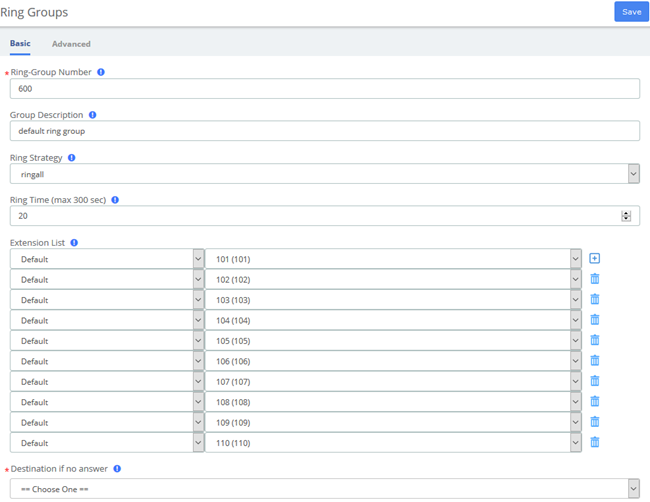
Figure 3-1-3 Ring groups interface
Table 3-1-2 Definition of add Ring groups interface
Item | Definition |
Basic | |
Ring-Group Number | The number users will dial to ring extensions in this ring group |
Group Description | Provide a descriptive title for this Ring Group. |
Ring Strategy | Ringall : Ring all available channels until one answers (default) Hunt: Take turns ringing each available extension Memoryhunt: Ring first extension in the list, then ring the 1 st and 2 nd extension, then ring 1 st and 2 nd and 3 rd extension in the list…etc. *-prim: there mode act as described above. However, if the primary extension (first in list) is occupied, the other extensions will not be rung. If the primary is CF unconditional, then all will be rung First available: ring only the first available channel Firstnotonphone: ring only the first channel which is not offhook-ignored CW. |
Ring Time (max 300 sec) | Time in seconds that the phones will ring. For all hunt style ring strategies, this is the time for each iteration of phone(s) that are rung. |
Extension List | List extensions to ring, one per line, or use the Extension Quick Pick below to insert them here. You can include an extension on a remote system, or an external number by suffixing a number with a ‘#’. Ex:2448089# would dial 2448089 on the appropriate trunk (see outbound routing) Extension without a ‘#’ will not ring a user’s Follow-Me. To dial Follow-Me, Queues and other numbers that are not extensions, put a ‘#’ at the end. |
Destination if no answer | If there is no answer, the call will be sent to the destination. |
Advanced | |
Announcement | Message to be played to the caller before dialing this group. To add additional recordings please use the “System Recordings” MENU to the left. |
Play Music On Hold | If you select a music on hold class to play, instead of ‘Ring’, they will hear that instead of Ringing while they waiting for someone to pick up. |
CID Name Prefix | You can optionally prefix the callerid name when ringing extensions in this group, ie: If you prefix with “Sales:”, a call from John Doe would display as “Sales: John Doe” on the extensions that ring. |
Alert Info | ALERT_INFO can be used for distinctive ring with SIP devices. |
Ignore CF Settings | When checked, agents who attempt to Call Forward will be ignored, this applies to CF, CFU and CFB. Extensions entered with ‘#’ at the end, for example to access the extension’s Follow-Me, might not honor this setting. |
Enable Call Pickup | Checking this will allow calls to the ring group to be picked up with the directed call pickup feature using the group number. When not checked, individual extensions that are part of the group can still be picked up by doing a directed call picked to the ringing extension, which works whether or not this is checked. |
Skip Busy Agent | When checked, agents who are on an occupied phone will skipped as if the line were returning busy. This means that call waiting or multi-line phones will not be presented with the call and in the various hunt style ring strategies, the next agent will be attempted. |
Confirm Calls | Enable this if you’re calling external numbers that need confirmation-eg, a mobile phone may go to voicemail which will pick up the call. Enabling this requires the remote side push 1 on their phone before the call is put through. This feature only works with the ringall ring strategy. |
Remote Announce | Message to be played to the person RECEIVING the call, if ‘Confirm Calls’ is enabled. To add additional recordings use the “System Recordings” MENU to the left |
Too-Late Announce | Message to be played to the person RECEIVING the call, if the call has already been accepted before they push 1. To add additional recordings use the “System Recordings” MENU to the left |
Mode | Default: Transmits the Callers CID if allowed by the trunk. Fixed CID Value: Always transmit the Fixed CID Value below. Outside Calls Fixed CID Value: Transmit the Fixed CID Value below on calls will continue to operate in default mode. Use Dialed Number: Transmit the number that was dialed as the CID for calls coming from outside. Internal extension to extension calls will continue to operate in default mode. There must be a DID on the inbound route for this. This will be BLOCKED on trunks that block foreign Caller ID Force Dialed Number: Transmit the number that was dialed as the CID for calls coming from outside. Internal extension to extension calls will be continue to operate in default mode. There must be a DID on the inbound route for this. This WILL be transmitted on trunks that block foreign CallerID |
Fixed CID Value | Fixed value to replace the CID with used with some of the modes above. Should be in a format of digits only with an option of E164 format using a leading “+”. |
Record Calls | You can always record calls that come into ring group, never record them, or allow the extension that answers to do on-demand recording. If recording is denied then one-touch on demand recording will be blocked. |
3.1.3 Follow Me
Follow Me (also known as Find Me / Follow Me or FMFM) allows you to redirect a call that is placed to one of your extensions to another location. You can program the system to ring the extension alone for a certain period of time, then ring some other destination(s), such as a mobile phone or a related extension, and then go to the original extension's voicemail if the call is not answered. Follow Me can also be used to divert calls to another extension without ringing the primary extension.
Select the PBX -> PBX Configuration -> Follow Me.
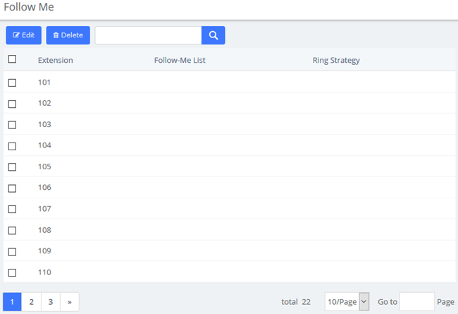
Figure 3-1-4 Follow Me interface
Select the extensions that you want to define.
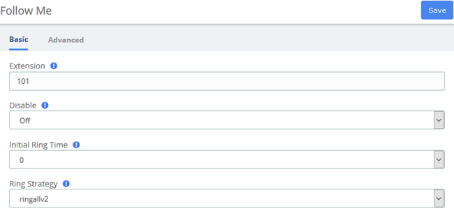
Figure 3-1-5 Follow Me User interface
Table 3-1-3 Definition of Follow Me
Item | Definition |
Basic | |
Extension | Edited extension |
Disable | By default (not checked) any call to this extension will go to this Follow-Me instead, including directory calls by name from IVRs. If checked, calls will go only to the extension. However, destinations that specify FollowMe will come here. Checking this box is often used in conjunction with VmX Locater, where you want a call to ring the extension, and then only if the caller chooses to find you do you want it to come here. |
Initial Ring Time | This is the number of seconds to ring the primary extension prior to proceeding to the follow-me list. The extension can also be included in the follow-me list. A 0 setting will bypass this |
Ring Strategy | Ringallv2: ring Extension for duration set in Initial Ring Time, and then, while continuing call to extension, ring Follow-Me List for duration set in Ring Time. Ringall: ring Extension for duration set in Initial Ring Time, and then, terminate call to extension, ring Follow-Me List for duration set in Ring Time. Hunt: take turns ringing each available extension Memoryhunt: ring first extension in the list, then ring the 1st and 2nd extension, then ring 1st 2nd and 3rd extension in the list…. etc. *-prim: these mode act as described above. However, if the primary extension (first in the list) is occupied, the other extensions will not be rung. If the primary is DND, it won’t be rung. If the primary is CF unconditional, then all will be rung Firstavailable: ring only the first available channel Firstavailable: ring only the first channel which is not off hook-ignore CW |
Ring Time (max 60 sec) | Time in second that the phones will ring. For all hunt style ring strategies, this is the time for each iteration of phone(s) that are rung |
Destination if no answer | Choose a destination when there is no answer. |
Follow-Me List | List extensions to ring, one per line, or use the Extension Quick Pick below. You can include an extension on a remote system, or an external number by suffixing a number with a pound (#). Ex:2448089# would dial 2448089 on the appropriate trunk (see Outbound Routing). |
Announcement | Message to be played to the caller before dialing this group. To add additional recordings please use the “System Recordings” MENU to the left. |
Play Music On Hold | If you select a Music on Hold class to play, instead of ‘Ring’, they will hear that instead of Ringing while they are waiting for someone to pick up. |
CID Name Prefix | You can optionally prefix the Caller ID name when ringing extensions in this group. Ie: if you prefix with “Sales:”, a call from John Doe would display as “Sales: John Doe” on the extensions that ring |
Alert Info | You can optionally include an Alert Info which can create distinctive ring on SIP phones. |
Advanced | |
Confirm Calls | Enable this if you’re calling external numbers that need confirmation, eg, a mobile phone may go to voicemail which pick up the call. Enabling this require the remote side push 1 on their phone before the calls is put through. This feature only works with the ringall/ringall-prim ring strategy. |
Remote Announce | Message to be played to the person RECEIVING the call, if ‘Confirm Calls” is enabled. To add additional recordings use the ‘System Recordings” MENU to the left |
Too-Late Announce | Message to be played to the person RECEIVING the call, if the call has already been accepted before they push 1. To add additional recordings use the ‘System Recordings” MENU to the left |
Mode | Default: Transmits the Caller CID if allowed by the trunk. Fixed CID Value: Always transmit the Fixed CID Value below. Outside Calls Fixed CID Value: Transmit the Fixed CID Value below on calls will continue to operate in default mode. Use Dialed Number: Transmit the number that was dialed as the CID for calls coming from outside. Internal extension to extension calls will continue to operate in default mode. There must be a DID on the inbound route for this. This will be BLOCKED on trunks that block foreign Caller ID Force Dialed Number: Transmit the number that was dialed as the CID for calls coming from outside. Internal extension to extension calls will be continue to operate in default mode. There must be a DID on the inbound route for this. This WILL be transmitted on trunks that block foreign CallerID |
Fixed CID Value | Fixed value to replace the CID with used with some of the modes above. Should be in a format of digits only with an option of E164 format using a leading “+”. |
3.2 Trunks
The "Trunks Module" is used to connect your FreePBX/Asterisk system to another VOIP system or VOIP device so that you can send calls out to and receive calls in from that system/device. You can create connections with Internet Telephone Service Providers ("ITSPs"), with other FreePBX/ Asterisk systems, with commercial VOIP phone systems, with FXO Gateways (a device that connects an ordinary telephone line with a VOIP phone system using a network connection), and with FXO cards (cards that are installed in your computer and allow you to connect a standard telephone line).
If you don't have a Trunk set-up, you can still make calls, but only to other extensions on your same phone system.
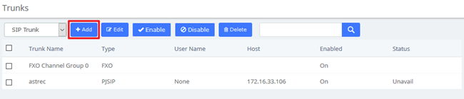
Figure 3-2-1 Add trunk interface

Figure 3-2-2 Add SIP Trunk
Table 3-2-1 Definition of add a SIP trunk
Item | Definition |
Basic | |
Enable Trunk | Check this to disable this trunk in all routes where it is used. |
Trunk Mode | Authentication mode of this trunk. |
Authentication | Usually, this will be set to "Outbound", which authenticates calls going out, and allows unauthenticated calls in from the other server. If you select "None", all calls from or to the specified SIP Server are unauthenticated. |
Trunk Name | Descriptive Name for this trunk. |
Host | Host settings for this device, almost always dynamic for endpoint. |
Transport | Transports which the device supports. |
From user | Rewrite the caller id |
From Domain | Example: proxy.provider.domain |
Enable NAT | Check this to enable or disable NAT |
Codec | Allow specified codecs, the available codecs are on the left options bar and the selected on the right. |
Advanced | |
DTMF Mode | Types of DTMF. |
Outbound CallerID | CallerID for calls placed out on this trunk Format: <#######>. You can also use the format: “hidden” <#######> to hide the CallerID sent out over Digital lines if supported (SIP/IAX). |
Maximum Channels | Controls the maximum number of outbound channels (simultaneous calls) that can be used on this trunk. To count inbound calls against this maximum, use the auto-generated context: as the inbound trunk's context. (see extensions_additional.conf) Leave blank to specify no maximum. |
Permanent Auth Rejection | Determines whether failed authentication challenges are treated as permanent. |
Forbidden Retry Interval | How long to wait before retry when receiving a 403 Forbidden response. |
Fatal Retry Interval | How long to wait before retry when receiving a fatal response. |
General Retry Interval | The interval between two registered request packets. |
Expiration | Expiration time for registrations in seconds. |
Max Retries | The times asterisk will attempt to register before give up. |
Qualify Frequency | Interval between two qualifies. |
Qualify Timeout | Timeout of qualify |
Contact User | Contact user to use in request. |
AOR Contact | Permanent contacts assigned to AoR. |
Support Path | When the button is enabled, registering request of outbound will advertise support for path header. |
Support T.38 UDPTL | Allow the device to support T.38 UDPTL |
T.38 UDPTL Error Correction | T.38 UDPTL error correction method |
T.38 UDPTL NAT | Whether NAT support is enabled on UDPTL sessions |
Fax Detect | When a CNG is detected, the session will be sent to the fax extension. |
Inband Progress | Determine whether chan_sip indicates ringing using inbound progress. |
Direct Media Method | Method for building direct media between endpoints. |
Trust Connected Line | Accept Connected Line updates from this endpoint. |
Send Connected Line | Send Connected Line updates to this endpoint |
Connected Line Method | Method used when updating connected line information. |
Direct Media | Determines whether media may flow directly between endpoints. |
RTP Symmetric | Enforce that RTP must be symmetric. |
Rewrite Contact | Allow contact header to be rewritten |
Asterisk Trunk Dial Options | Asterisk Dial command options to be used when calling out this trunk. To override the Advanced Settings default, check the box and then provide the required options for this trunk |
Context | (Experts Only) Set the context that calls will originate from. Leaving this as from-internal unless you know what you’re doing. |
Continue if Busy | Normally the next trunk is only tried upon a trunk being ‘Congested’ in some form, or unavailable. Checking this box will force a failed call to always continue to the next configured trunk or destination even when the channel reports BUSY or INVALID NUMBER. |
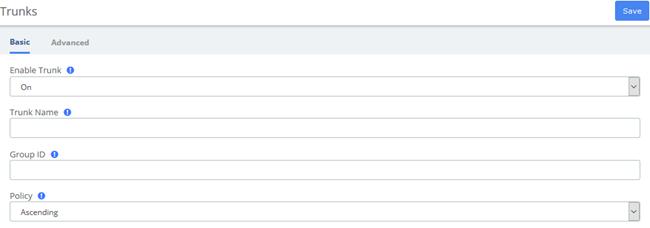
Figure 3-2-3 Add FXO Trunk
Table 3-2-2 Definition Add FXO Trunk
Item | Definition |
Basic | |
Enable Trunk | Check this to disable this trunk in all routes where it is used. |
Trunk Name | Descriptive Name for this trunk. |
Group ID | FXO channels are referenced either by a group number or channel number (which is defined in chan_dahdi.conf). The default setting is g0 (group zero). |
Policy | Used to make FXO trunks decisions, help determine the ringing order among multiple members of group |
Member of Groups | Adding FXO ports into trunk groups allow automatic selection of the selected idle port for outgoing calls. |
Advanced | |
Outbound CallerID | CallerID for calls placed out on this trunk Format: <#######>. You can also use the format: “hidden” <#######> to hide the CallerID sent out over Digital lines if supported (SIP/IAX). |
CID Options | Determines what CIDs will be allowed out this trunk. IMPORTANT: EMERGENCY CIDs defined on an extension/device will ALWAYS be used if this trunk is part of an EMERGENCY Route regardless of these settings. Allow Any CID: all CIDs including foreign CIDS from forwarded external calls will be transmitted. Block Foreign CIDs: blocks any CID that is the result of a forwarded call from off the system. CIDs defined for extensions/users are transmitted. Remove CNAM: this will remove CNAM from any CID sent out this trunk Force Trunk CID: Always use the CID defined for this trunk except if part of any EMERGENCY Route with an EMERGENCY CID defined for the extension/device. Intra-Company Routes will always transmit an extension’s internal number and name. |
Maximum Channels | Controls the maximum number of outbound channels (simultaneous calls) that can be used on this trunk. Inbound calls are not counted against the maximum. Leave blank to specify no maximum. |
Asterisk Trunk Dial Options | Asterisk Dial command options to be used when calling out this trunk. To override the Advanced Settings default, check the box and then provide the required options for this trunk |
Context | (Experts Only) Set the context that calls will originate from. Leaving this as from-internal unless you know what you’re doing. |
Continue if Busy | Normally the next trunk is only tried upon a trunk being ‘Congested’ in some form, or unavailable. Checking this box will force a failed call to always continue to the next configured trunk or destination even when the channel reports BUSY or INVALID NUMBER. |
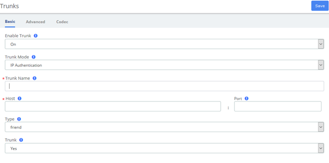
Figure 3-2-4 Add IAX2 Trunk
Table 3-2-3 Definition of Add IAX2 Trunk
Item | Definition |
Basic | |
Enable Trunk | Check this to disable this trunk in all routes where it is used. |
Trunk Mode | Authentication mode of this trunk. |
Trunk Name | Descriptive Name for this trunk |
Host | Host settings for this device, almost always dynamic for endpoint. |
Type | Asterisk connection type. There are three type you can choose, friend, peer and user.usually friend for endpoint. |
Trunk | Use IAX2 trunk with this host. |
Advanced | |
Outbound CallerID | CallerID for calls placed out on this trunk Format: <#######>. You can also use the format: “hidden” <#######> to hide the CallerID sent out over Digital lines if supported (SIP/IAX). |
CID Options | Determines what CIDs will be allowed out this trunk. IMPORTANT: EMERGENCY CIDs defined on an extension/device will ALWAYS be used if this trunk is part of an EMERGENCY Route regardless of these settings. Allow Any CID: all CIDs including foreign CIDS from forwarded external calls will be transmitted. Block Foreign CIDs: blocks any CID that is the result of a forwarded call from off the system. CIDs defined for extensions/users are transmitted. Remove CNAM: this will remove CNAM from any CID sent out this trunk Force Trunk CID: Always use the CID defined for this trunk except if part of any EMERGENCY Route with an EMERGENCY CID defined for the extension/device. Intra-Company Routes will always transmit an extension’s internal number and name. |
Maximum Channels | Controls the maximum number of outbound channels (simultaneous calls) that can be used on this trunk. To count inbound calls against this maximum, use auto-generated context: from-trunk-[trunkname] as the inbound trunk’s context. (see extesions_additional.conf) Leave blank to specify no maximum. |
Outbound Dial Prefix | The outbound dialing prefix is used to prefix a dialing string to all outbound calls placed on this trunk. For example, if this trunk is behind another PBX or is a Centrex line, then you would put 9 here to access an outbound line. Another common use is to prefix calls with 'w' on a POTS line that need time to obtain dial tone to avoid eating digits. Most users should leave this option blank. |
Qualifyfreq OK | Frequency in milliseconds to send qualify messages to the endpoint. |
Qualifyfreq Not OK | Frequency in milliseconds to send qualify messages to the endpoint. |
Qualify | Setting to yes (equivalent to 2000 msec) will send an OPTIONS packet to the endpoint periodically (default every minute). Used to monitor the health of the endpoint. If delays are longer then the quality time, the endpoint will be taken offline and considered unreachable. Can be set to a value which is the msec threshold. Setting to no will turn this off. Can also be helpful to keep NAT pinholes open. |
Asterisk Trunk Dial Options | Asterisk Dial command options to be used when calling out this trunk. To override the Advanced Settings default, check the box and then provide the required options for this trunk. |
Context | (Experts Only) Set the context that calls will originate from. Leaving this as from-internal unless you know what you’re doing. |
Continue if Busy | Normally the next trunk is only tried upon a trunk being ‘Congested’ in some form, or unavailable. Checking this box will force a failed call to always continue to the next configured trunk or destination even when the channel reports BUSY or INVALID NUMBER. |
Codec | |
Audio Codecs | You can choose specific audio codecs here |
Video Codecs | You can choose specific video codecs here |
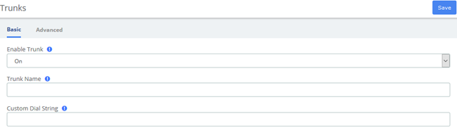
Figure 3-2-5 Add CUSTOM Trunk interface
Table 3-2-4 Definition of Add CUSTOM Trunk
Item | Definition |
Basic | |
Enable Trunk | Check this to disable this trunk in all routes where it is used. |
Trunk Name | Descriptive Name for this trunk |
Custom Dial String | Define the custom Dial String. Include the token $OUTNUM$ wherever the number to dial should go. examples: CAPI/XXXXXXXX/$OUTNUM$ H323/$OUTNUM$@XX.XX.XX.XX OH323/$OUTNUM$@XX.XX.XX.XX:XXXX vpb/1-1/$OUTNUM$ |
Advanced | |
Outbound CallerID | CallerID for calls placed out on this trunk Format: <#######>. You can also use the format: “hidden” <#######> to hide the CallerID sent out over Digital lines if supported (SIP/IAX). |
CID Options | Determines what CIDs will be allowed out this trunk. IMPORTANT: EMERGENCY CIDs defined on an extension/device will ALWAYS be used if this trunk is part of an EMERGENCY Route regardless of these settings. Allow Any CID: all CIDs including foreign CIDS from forwarded external calls will be transmitted. Block Foreign CIDs: blocks any CID that is the result of a forwarded call from off the system. CIDs defined for extensions/users are transmitted. Remove CNAM: this will remove CNAM from any CID sent out this trunk Force Trunk CID: Always use the CID defined for this trunk except if part of any EMERGENCY Route with an EMERGENCY CID defined for the extension/device. Intra-Company Routes will always transmit an extension’s internal number and name. |
Maximum Channels | Controls the maximum number of outbound channels (simultaneous calls) that can be used on this trunk. Inbound calls are not counted against the maximum. Leave blank to specify no maximum. |
Asterisk Trunk Dial Options | Asterisk Dial command options to be used when calling out this trunk. To override the Advanced Settings default, check the box and then provide the required options for this trunk |
Context | (Experts Only) Set the context that calls will originate from. Leaving this as from-internal unless you know what you’re doing. |
Continue if Busy | Normally the next trunk is only tried upon a trunk being ‘Congested’ in some form, or unavailable. Checking this box will force a failed call to always continue to the next configured trunk or destination even when the channel reports BUSY or INVALID NUMBER. |
3.3 Call Control
3.3.1 Inbound Routes
When a call comes into your system from the outside, it will usually arrive along with information about the telephone number that was dialed (also known as the "DID") and the Caller ID of the person who called.
The Inbound Routes module is used to tell your system what to do with calls that come into your system on any trunk that has the "context=from-trunk" parameter in the PEER details.
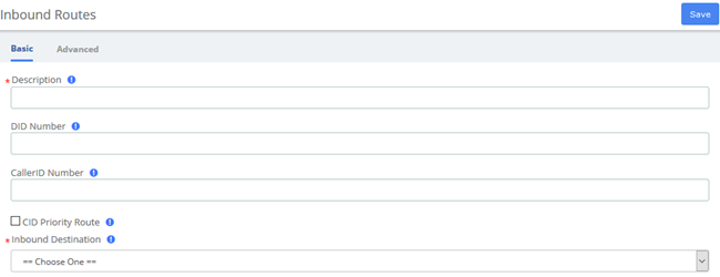
Figure 3-3-1 Add incoming Route interface
Table 3-3-1 Definition of Add incoming Route
Item | Definition |
Basic | |
Description | Provide a meaningful description of what this incoming route is |
DID Number | Define the expected DID Number if your trunk passes DID on incoming calls. Leaving this blank to match calls with any or no DID info. You can also use a pattern match (eg_2[345]X) to match a range of numbers. |
CallerID Number | Define the CallerID Number to be matched on incoming calls. Leave this field blank to match any or no CID info. In addition to standard dial sequences, you can also put Private, Blocked, Unknown, Restricted, Anonymous and Unavailable in order to catch these special cases if the Telco transmits them. |
CID Priority Route | This effects CID ONLY routes where no DID is specified. If checked, calls with this CID will routed to this route, even if there is a route to the DID that was called. Normal behavior is for the DID route to take the calls. If there is a specific DID/CID route for this CID, that route will still take the call when that DID is called. |
Inbound Destination | Indicates extension, Ring Group, Voicemail or other destination to which the call is suppoesd to be directed when the outside callers have called specified DID Number |
Advanced | |
Alert Info | ALERT_INFO can be used for distinctive ring with SIP devices. |
CID name prefix | You can optionally prefix the CallerID name. ie: If you prefix with “Sales:”, a call from john Doe would display as “Sales: John Doe” on the extension that ring |
Music On Hold | Set the MoH class that will be used for calls that come in on this route. For example, choose a type appropriate for routes coming in from a country which may have announcements in their language. |
Signal RINGING | Some devices or providers require RINGING to be sent before ANSWER. You’ll notice this happening if you can send calls directly to a phone, but if you send it to an IVR, it won’t connect the call. |
Pause Before Answer | An optional delay to wait before processing this route. Setting this value will delay the channel from answering the call. This may be handy if external fax equipment or security systems are installed in parallel and you would like them to be able to seize the line. |
Privacy Manager | If no CallerID has been received, Privacy Manager will ask the caller to enter their phone number. If an user/extension has Call Screening enabled, the incoming caller will be prompted to say their name when the call reaches the user/extension. |
Source | Source can be added in Caller Name Lookup Sources section. |
Language | Allows you to set the language for this DID. |
Fax Detect | Attempt to detect faxes on this DID. No: No attempts are made to auto-determine the call type; all calls sent to destination below. Use this option if this DID is used exclusively for voice OR fax. Yes: try to auto determine the type of call; route to the fax destination if call is a fax, otherwise send to regular destination. Use this option if you receive both voice and fax calls on this line. |
3.3.2 Outbound Routes
The Outbound Routes Module is used to tell your FreePBX/Asterisk system which numbers your phones are permitted to call and which Trunk to send the calls to.
Generally, a FreePBX/Asterisk system will have a Restricted route which designates certain numbers that can never be dialed (such as 900 and 976 numbers), an Emergency route to use for routing110 calls, and a route for ordinary calls. A phone system might also have special routes for interoffice calls, international calls, and other special circumstances
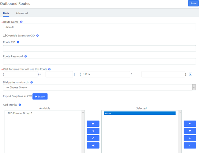
Figure 3-3-2 Outbound Routes interface
Table 3-3-2 Definition of Outbound Routes
Item | Definition |
Basic | |
Route Name | Name of this route. Should be used to describe what type of calls this route matches (for example, 'local' or 'longdistance'). |
Route CID | Optional Route CID to be used for this route. If set, this will override all CIDS specified except: l extension/device EMERGENCY CIDs if this route is checked as an EMERGENCY Route l trunk CID if trunk is set to force it's CID l Forwarded call CIDs (CF, Follow Me, Ring Groups, etc) l Extension/User CIDs if checked |
Route Password | Optional: A route can prompt users for a password before allowing calls to progress. This is useful for restricting calls to international destinations or 1-900 numbers. A numerical password, or the path to an Authenticate password file can be used. Leave this field blank to not prompt for password. |
Dial Patterns that will use this Route | A Dial Pattern is a unique set of digits that will select this route and send the call to the designated trunks. If a dialed pattern matches this route, no subsequent routes will be tried. If Time Groups are enabled, subsequent routes will be checked for matches outside of the designated time(s). Rules: X matches any digit from 0-9 Z matches any digit from 1-9 N matches any digit from 2-9 [1237-9] matches any digit in the brackets (example: 1,2,3,7,8,9). wildcard, matches one or more dialed digits Prepend: Digits to prepend to a successful match. If the dialed number matches the patterns specified by the subsequent columns, then this will be prepended before sending to the trunks. Prefix: Prefix to remove on a successful match. The dialed number is compared to this and the subsequent columns for a match. Upon a match, this prefix is removed from the dialed number before sending it to the trunks. Match pattern: The dialed number will be compared against the prefix + this match pattern. Upon a match, the match pattern portion of the dialed number will be sent to the trunks. CallerID: If CallerID is supplied, the dialed number will only match the prefix + match pattern if the CallerID being transmitted matches this. When extensions make outbound calls, the CallerID will be their extension number and NOT their Outbound CID. The above special matching sequences can be used for CallerID matching similar to other number matches. |
Dial patterns wizards | These options provide a quick way to add outbound dialing rules. Follow the prompts for each. Lookup local prefixes This looks up your local number on ww.localcallingguide.com (NA-only), and sets up so you can dial either 7, 10 or 11 digits (5551234, 6135551234, 16135551234) to access this route. Upload from CSV Upload patterns from a CSV file replacing existing entries. If there are no headers then the file must have 4 columns of patterns in the same order as in the GUI. You can also supply headers: prepend, prefix, match pattern and callerid in the first row. If there are less than 4 recognized headers then the remaining columns will be blank. |
Add Trunks | Trunks used by this outbound route, the available trunks are on the left options bar and the selected on the right. |
Advanced | |
Route Type | Optional: Selecting Emergency will enforce the use of a device |
Music On Hold | You can choose which music category to use. For example, choose a type appropriate for a destination country which may have announcements in the appropriate language. |
Time Group | If this route should only be available during certain times then Select a Time Group created under Time Groups. The route will be ignored outside of times specified in that Time Group. If left as default of Permanent Route then it will always be available. |
Route Position | Where to insert this route or relocate it relative to the other routes. |
PIN Set | Optional: Select a PIN set to use. If using this option, leave the Route Password field blank. |
Optional Destination on Congestion | If all the trunks fail because of Asterisk ‘CONGESTION’ dial status you can optionally go to a destination such as a unique recorded message or anywhere else. This destination will NOT be engaged if the trunk is reporting busy, invalid numbers or anything else that would imply the trunk was able to make an ‘intelligent’ choice about the number that was dialed. The ‘Normal Congestion’ behavior is to play the ‘ALL Circuits Busy’ recording or other options configured in the route Congestion Messages module when installed. |
3.3.3 Call Restrictions
Black List
The blacklist module is used to add a phone number to a blacklist or remove a phone number from a blacklist. You can also choose to blacklist any blocked or unknown calls.
When a number is blacklisted, any calls with that number in the Caller ID field received by the system will be routed to the disconnected record.
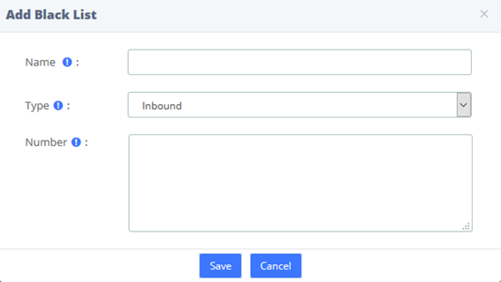
Figure 3-3-3 Blacklist interface
Table 3-3-3 Definition of Blacklist
Item | Definition |
Name | Name of this blacklist rule. |
Type | Which type the rule applies to, including Inbound/Outbound/Both |
Number | Enter the number you want to block, you can input sets of digits that match the Dial Pattern Rules. |
White List
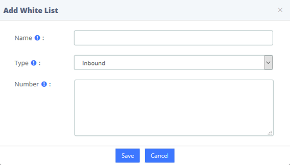
Figure 3-3-4 Whitelist interface
Table 3-3-4 Definition of Whitelist
Item | Definition |
Name | Name of this whitelist rule. |
Type | Which type the rule applies to, including Inbound/Outbound/Both |
Number | Enter the number you want to add into whitelist, you can input sets of digits that match the Dial Pattern Rules. |
3.3.4 Set CallerID
You can change name and number of incoming call display.

Figure 3-3-5 Set CallerID interface
Table 3-3-5 Definition of CallerID
Item | Definition |
Description | Provide a title for it |
CallerID Name | The callserID name will be changed to it. |
CallerID Number | The callserID number will be changed to it. |
Destination | Destination the call will be sent to after CID has been processed. |
3.3.5 Call Flow Control
The Call Flow Control module is used to create a single destination that can act as a switch that can be toggled by anyone who has access to a local phone. It is commonly used to allow phone system users to manually switch between "Daytime Mode" and "Nighttime Mode."
Call Flow Control should not be confused with Time Conditions. While both of these modules relate to call flow, Call Flow Control is designed to be a manual switch, while a Time Condition is designed to be a scheduled, automatic switch.
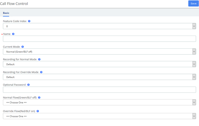
Figure 3-3-6 Call flow control interface
Table 3-3-6 Definition of Call flow control
Item | Definition |
Feature Code Index | There are a total of 10 Feature code objects,0-9, each can control a call flow and be toggled using the call flow toggled feature code plus the index |
Name | Description for this Call Flow Toggle Control |
Current Mode | This will change the current state for this Call Flow Toggle Control, or set the initial state when creating a new one. |
Recording for Normal Mode | Message to be played in normal mode (Green/BLF off) To add additional recordings use the “System Recordings” MENU to the left |
Recording for Override Mode | Message to be played in override mode (Green/BLF off) To add additional recordings use the “System Recordings” MENU to the left |
Optional Password | You can optionally include a password to authenticate before toggling the call flow. If left blank anyone can use the feature code and it will be un-protected |
Normal Flow (Green/BLF off) | Destination to use when set to Normal Flow (Green/BLF off) mode |
Override Flow (Red/BLF on) | Destination to use when set to Override Flow (Red/BLF off) mode |
3.3.6 Time Conditions
You can create various time conditions and use these time conditions in conjunction with your Inbound Route to individualize each of the incoming trunk’s behavior.
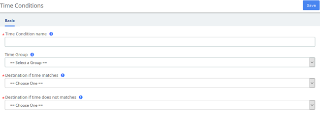
Figure 3-3-7 Time Conditions interface
Table 3-3-7 Definition of add Time Conditions
Item | Definition |
Time Condition name | Give this Time Condition a brief name to help you identify it. |
Time Group | Select a time group created under Time Groups. Matching times will be sent to matching destination. If no group is selected, call will always go to no-match destination. |
Destination if time matches | The destination the call will be sent to when the time matches. |
Destination if time does not match | The destination the call will be sent to when the time doesn’t match. |
3.3.7 Time Groups
The Time Groups Module is used to define periods of time that can then be selected in the Time Conditions module or Outbound Routes module.
For example, you might create a Time Group called "Lunch" that might start at 12:00 p.m and end at 1:00 p.m. You could then create a Time Condition that would use the Lunch Time Group to send calls to voicemail during lunch, and to a ring group at other times.
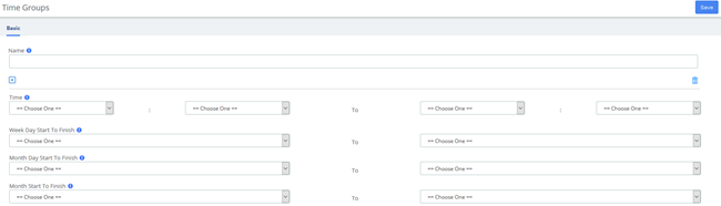
Figure 3-3-8 Time Groups interface
Table 3-3-8 Definition of Time Conditions
Item | Definition |
Name | It will display as the name of time group |
Time | Choose a time interval. |
Week Day Start To Finish | Start and end times of one week. |
Month Day Start To Finish | Start and end times of one month. |
Month Start To Finish | Start and end times of one year. |
3.3.8 PIN Sets
UC Series allows you to require callers to dial a password before an outbound call will go through. You can require a password on all calls, or only on calls to certain numbers.
The PIN Sets Module allows you to create define groups and then assign a list of passwords to each group. You can then restrict certain calls to certain groups by going to the Outbound Routes Module and limiting the route to a certain PIN Set group. Each Outbound Route can be limited to just one PIN Set group. So, if you want to allow more than one PIN Set group to make a certain type of call, just create a duplicate Outbound Route and assign the second Outbound Route to a different PIN Set Group.

Figure 3-3-9 PIN Sets Interface
Table 3-3-9 Definition of add PIN Set
Item | Definition |
Name | Name of the pin sets. |
Record In CDR | Select this box if you would like to record the PIN in the call detail records when used. |
PIN List | Enter a list of one more PINs. One PIN per line. |
3.3.9 FXO Channels DIDs
The FXO Channel DIDs module allows you to assign a DID or phone number to specific analog channels.
Unlike SIP or PRI trunks, analog lines do not send a DID or dialed number to the PBX. Since the PBX routes all inbound calls based on the DID or number dialed, we need to map each analog port or channel to a fake number so we can match that number to an Inbound Route number and route your calls.
Each channel can be mapped to the same phone number if you want all calls on the analog lines to go to the same destination. This would be a common scenario if you have multiple POTS lines that are on a hunt group from your provider.

Figure 3-3-10 Add FXO Channel interface
Table 3-3-10 Definition of Add FXO Channel
Item | Definition |
Channel | The FXO Channel number to map to a DID |
Description | A useful description this channel |
DID | The DID that this channel represents. The incoming call on this channel will be treated as if it came in with this DID and can be managed with Inbound Routing on DIDs |
3.3.10 AutoCLIP Route
Generally, in the enterprise's telephony system, incoming calls are routed to IVR, ring groups, queues, and so on instead of specific extensions. AutoCLIP can redirect calls to the extension of the original caller instead of the automated attendant or the default ring group.
You may encounter situations that when you use an internal extension to call a client or colleague and they don't answer the call in time. By the time he/she dials back, the IP telephony system directs him/her to the default inbound routing destination such as IVR, making it difficult for callers who are not in touch to find you. AutoCLIP deals with this by ignoring the routing destination and redirecting this call to the original extension (your IP Phone line) according to stored records of outgoing calls in the AutoCLIP route table. This feature will retain many opportunities and possibilities for customers.
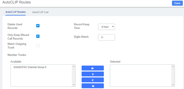
Figure 3-3-11 Add FXO Channel interface
Table 3-3-11 Definition of AutoCLIP Route
Item | Definition |
Delete Used Records | If enabled, when an AutoCLIP record is matched, it will be automatically deleted afterwards. |
Record Keep Time | This sets how long each record will be kept in the AutoCLIP List. |
Only Keep Missed Call Records | If enabled, the system will only keep records of calls that are not answered by the called party in the AutoCLIP list. Note: PSTN line will keep records of all calls whether this option is enabled or disabled. |
Digits Match | Define how many digits from the last digit of the incoming phone number will be used to match the AutoCLIP record. If the number has fewer digits than the value defined here, all digits will be matched. |
Match Outgoing Trunk | If enabled, only the incoming call that came to the PBX through the same trunk which made the call will be match against the AutoCLIP List. |
Member Trunks | This defines AutoCLIP Route will apply to which trunk and which trunk's record will be kept in the AutoCLIP list. If no trunk's selected, AutoCLIP will stop working. |
3.4 Call Features
3.4.1 IVR
The IVR module allows you to create one or more IVRs ("Interactive Voice Response" systems or Auto Attendants). You can then route calls to the IVR and play a recording prompting callers what options to enter, such as “press 1 for sales and press 2 for the company directory.” An IVR can also route calls to another IVR, or in other words, a sub-menu. As a general rule, you never want more than five or six options in a single IVR, or it will become too confusing to navigate. It is better to only include a few options at a single menu level, and route callers to a sub-menu for more choices.
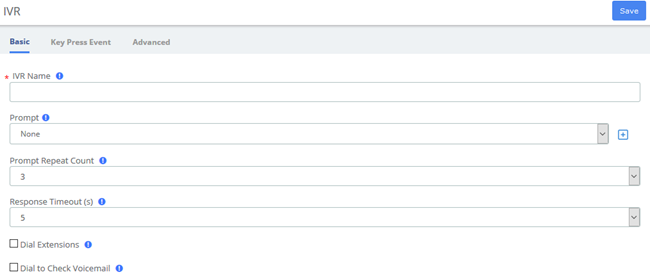
Figure 3-4-1 IVR interface
Table 3-4-1 Definition of add IVR
Item | Definition |
Basic | |
IVR Name | Name of this IVR |
Prompt | The prompt will be played when a call reaches the IVR. |
Prompt Repeat Count | The number of times that the prompt will be played. |
Response Timeout (s) | The number of seconds to wait for a digit input after prompt. |
Dial Extensions | Allow the caller to dial extension directly. |
Dial to Check Voicemail | If enabled, the caller will be allowed to dial '*97' to check voicemail. |
Advanced | |
Invalid Retries | Number of time to retry when receiving an invalid/unmatched response from the caller |
Invalid Retry Recording | Prompt to be played when an invalid/unmatched response is received, before prompt the caller to try again |
Append Announcement on Invalid | After playing Invalid Retry Recording the system will replay mail IVR Announcement |
Return on Invalid | Check this box to have this option return to a parent IVR if it was called from a parent IVR. If not, it will go to the chosen destination. The return path will be to any IVR that was in the call path prior to this IVR which could lead to strange result if there was an IVR called in the call path but not immediately before this. |
Invalid Recording | Prompt to be played before sending the caller to an alternate destination due to the caller pressing 0 or receiving the maximum amount of invalid/unmatched responses (as determined by Invalid Retries) |
Timeout Retry Recording | Prompt to be played when a timeout occurs, before prompting the caller to try again |
Append Announcement on Timeout | After playing the Timeout Retry Recording the system will replay the main IVR Announcement. |
Return on Timeout | Check this box to have this option return to a parent IVR if it was called from a parent IVR. If not, it will go to the chosen destination. The return path will be to any IVR that was in the call path prior to this IVR which could lead to strange result if there was an IVR called in the call path but not immediately before this |
Timeout Recording | Prompt to be played before sending the caller to an alternate destination due to the caller pressing 0 or receiving the maximum amount of invalid/unmatched responses (as determined by Invalid Retries) |
Return to IVR after VM | If checked, upon exiting voicemail a caller will be returned to this IVR if they got a user voicemail |
3.4.2 Queues
The Queues module is a more advanced version of the Ring Groups module. Like the Ring Groups module, the Queues module is used to create an extension number that your users can dial in order to ring multiple extensions at the same time. It also creates a destination to which you can send calls that will ring those multiple extensions.
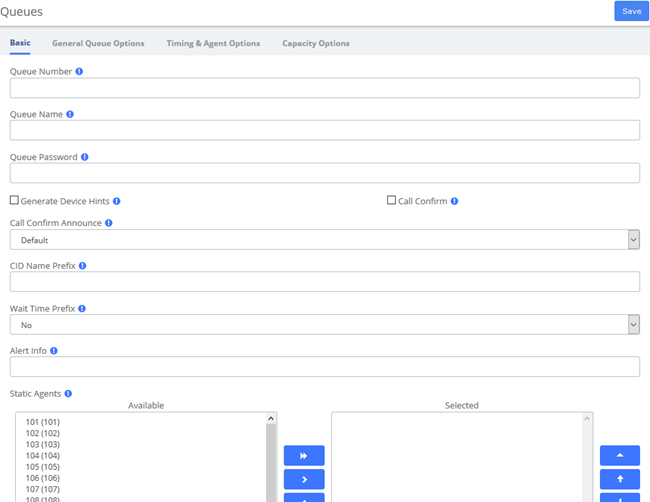
Figure 3-4-2 Queues interface
Table 3-4-2 Definition of Queues
Item | Definition |
Basic | |
Queue Number | Use this number to dial into the queue, or transfer callers to this number to put them into the queue. Agents will dial this queue number plus* to log the queue, and this queue number plus** to log out the queue. For example, if the queue number is 123: 123*=log in 123**=log out |
Queue Name | Give the queue a brief name to help you identify it. |
Queue Password | You can require agents to enter a password before they can log in to this queue. This setting is optional. The password is only used when logging in with the legacy queue no* code. When using the toggle codes, you must use the Restrict Dynamic Agents option in conjunction with the Dynamic Members list to control access. |
Generate Device Hints | If checked, individual hints and dialplan will be generated for each SIP and IAX2 device that could be part of this queue. These are used in conjunction with programmable BLF status as to the current state, the format of this hints is *45ddd*qqq Where *45 is the currently define toggle feature code, ddd is the device number (typically the same as the extension number) and qqq is this queue’s number |
Call Confirm | If checked, any queue member that is actually an outside telephone number, or any extension Follow-Me or call forwarding that are pursued and leave the PBX will be forced into Call Confirmation mode where the member must acknowledge the call before it is answered and delivered. |
Call Confirm Announce | Announcement played to the Queue Member announcing the Queue call and requesting confirmation prior to answering. If set to default, the standard call confirmation default message will be played unless the number is reached through a Follow-Me and this is an alternate message provided in the Follow-Me. This message will override any other message specified. To add additional recordings please use the “System Recordings” MENU. |
CID Name Prefix | You can optionally prefix the CallerID name of callers to the queue. ie: If you prefix with “Sales:”, a call from John Doe would display as “Sales: John Doe” on the extensions that ring. |
Wait Time Prefix | When set to Yes, the CID Name will be prefix with the total wait time in the queue so the answering agent is aware how long they have waited. It will be rounded to the nearest minute, in the form of Mnn: where nn is the number of minutes. If the call is subsequently transferred, the wait time will reflect the time since it first entered the queue or reset if the call is transferred to another queue with this feature set. |
Alert Info | ALERT_INFO can be used for distinctive ring with SIP device. |
Static Agents | Static agents are extensions that are assumed to always be on the queue. Static agents do not need to 'log in' to the queue, and cannot 'log out' of the queue. List extensions to ring, one per line. You can include an extension on a remote system, or an external number (Outbound Routing must contain a valid route for external numbers). You can put a "," after the agent followed by a penalty value, see Asterisk documentation concerning penalties. An advanced mode has been added which allows you to prefix an agent number with S, X, Z, D or A. This will force the agent number to be dialed as an Asterisk device of type SIP, IAX2, ZAP, DAHDi or Agent respectively. This mode is for advanced users and can cause known issues in PBX as you are by-passing the normal dialplan. If your 'Agent Restrictions' are not set to 'Extension Only' you will have problems with subsequent transfers to voicemail and other issues may also exist. (Channel Agent is deprecated starting with Asterisk 1.4 and gone in 1.6+.) |
Dynamic Members | Dynamic Members are extensions or callback numbers that can log in and out of the queue. When a member logs in to a queue, their penalty in the queue will be as specified here. Extensions included here will NOT automatically be logged in to the queue. |
Restrict Dynamic Agents | Restrict dynamic queue member logins to only those listed in the Dynamic Members list above. When set to Yes, members not listed will be DENIED ACCESS to the queue. |
Agent Restrictions | When set to ‘Call as Dialed’ the queue will call an extension just as if the queue were another user. Any Follow-Me or Call Forward states active on the extension will result in the queue call following these call paths. This behavior has been the standard queue behavior on past PBX versions. When set to ‘No Follow-Me or Call Forward’, all agents that are extensions on the system will be limited to ring their extensions only. Follow-Me and Call Forward settings will be ignored. Any other agent will be called as dialed. This behavior is similar to how extensions are dialed in ringgroups When set to ‘Extensions Only’ the queue will dial Extensions as described for ‘No Follow –Me or Call Forward’. Any other number entered for an agent that is NOT a valid extension will be ignored. No error checking is provided when entering a static agent or when logging on as a dynamic agent, the call will simply be blocked when the queue tries to call it. For dynamic agents, see the ‘Agent Regex filter’ to provide some validation. |
General Queue Options | |
Ring Strategy | Ringall: ring all available agents until one answers (default) Leastrecent: ring agent which was least recently called by this queue Fewestcalls: ring the agent with fewest completed calls from this queue Random: ring random agent Rrmemory: round robin with memory, remember where we left off last ring pass Rrordered: same as rrmemory, except the queue member where order from config file is preserved Linear: rings agents in the order specified, for dynamic agents in the order they logged in Wrandom: random using the member’s penalty as a weighting factor, see asterisk documentation for specifics. |
Autofill | Starting with Asterisk 1.4, if this is checked, and multiple agents are available, Asterisk will send one call to each waiting agent(depending on the ring strategy). Otherwise, it will hold all calls while it tries to find an agent for the top call in the queue making other calls wait. This was the behavior in Asterisk 1.2 and has no effect in 1.2. See Asterisk documentation for more details of this feature. |
Skip Busy Agents | When set to 'Yes' agents who are on an occupied phone will be skipped as if the line were returning busy. This means that Call Waiting or multi-line phones will not be presented with the call and in the various hunt style ring strategies, the next agent will be attempted. When set to 'Yes + (ringinuse=no)' the queue configuration flag 'ringinuse=no' is set for this queue in addition to the phone's device status being monitored. This results in the queue tracking remote agents (agents who are a remote PSTN phone, called through Follow-Me, and other means) as well as PBX connected agents, so the queue will not attempt to send another call if they are already on a call from any queue. When set to 'Queue calls only (ringinuse=no)' the queue configuration flag 'ringinuse=no' is set for this queue also but the device status of locally connected agents is not monitored. The behavior is to limit an agent belonging to one or more queues to a single queue call. If they are occupied from other calls, such as outbound calls they initiated, the queue will consider them available and ring them since the device state is not monitored with this option. WARNING: When using the settings that set the 'ringinuse=no' flag, there is a NEGATIVE side effect. An agent who transfers a queue call will remain unavailable by any queue until that call is terminated as the call still appears as 'inuse' to the queue UNLESS 'Agent Restrictions' is set to 'Extensions Only'. |
Queue Weight | Gives queue a ‘weight’ option, to ensure calls waiting in a higher priority queue will deliver its calls first if there are agents common to both queues. |
Music on Hold Class | Music (MoH) played to the caller while they wait in line for an available agent. Choose “inherit” if you want the MoH class to be what is currently selected, such as by the inbound route. MoH Only will play music until the agent answers. Agent Ringing will play MoH until an agent’s phone is presented with the call and is ringing. If they don’t answer MoH will return. Ring only makes callers hear a ringing tone instead of MoH ignoring any MoH class selected as well as any configured periodic announcements. This music is defined in the “Music on Hold” Menu. |
Join Announcement | Announcement played to callers prior to joining the queue. This can be skipped if there are agents ready to answer a call (meaning they still may be wrapping up from a previous call) or when they are free to answer the call right now. To add additional recordings please use the “System Recordings” MENU. |
Caller Volume Adjustment | Adjust the recording volume of the caller. |
Agent Volume Adjustment | Adjust the recording volume of the queue member (Agent). |
Mark calls answered elsewhere | Enabling this option, all calls are marked as ‘answered elsewhere’ when cancelled. The effect is that missed queue calls are *not* shown on the phone(if the phone support it) |
Timing & Agent Options | |
Max Wait Time | The maximum number of seconds a caller can wait in a queue before being pulled out.(0 for unlimited). |
Max Wait Time Mode | Asterisk timeoutpriority. In ‘Strict’ mode, when the ‘Max Wait Time’ of a caller is hit, they will be pulled out of the queue immediately. In ‘Loose’ mode, if a queue stops ringing with this call, then we will wait until the queue stops ringing this queue number or otherwise the call is rejected by the queue member before taking the caller out of the queue. This means that the ‘Max Wait Time’ could be as long as ‘Max Wait Time’+’Agent Timeout’ combined. |
Agent Timeout | The number of seconds an agent’s phone can ring before we consider it a timeout. Unlimited or other timeout values may still be limited by system ringtime or individual extension defaults. |
Agent Timeout Restart | If timeout restart is set to yes, then the time out for an agent to answer is reset if a BUSY or CONGESTION is received. This can be useful if agents are able to cancel a call with reject or similar |
Retry | The number of seconds we wait before trying all the phones again. Choosing “No Retry” will exit the queue and go to the fail-over destination as soon as the first attempted agent time-out, additional agents will not be attempted. |
Wrap-Up-Time | After a successful call, how many seconds to wait before sending a potentially free agent another call (default is 0, or no delay) If using Asterisk 1.6+, you can also set the ‘Honor Wrapup Time Across Queues setting (Asterisk: shared_lastcall) on the Advanced Settings page so that this is honored across queues for members logged on to multiple queues. |
Member Delay | If you wish to have a delay before the member is connected to the caller (or before the member hears any announcement messages), set this to the number of seconds to delay. |
Agent Announcement | Announcement played to the Agent prior to bridging in the caller. Example : ”the Following call is from the Sales Queue” or “This call is from the Technical Support Queue”. To add additional recordings please use the “System Recordings” MENU. Compound recordings composed of 2 or more sound files are not displayed as options since this feature can not accept such recordings. |
Report Hold Time | If you wish to report the caller’s hold time to the member before they are connected to the caller, set this to yes. |
Auto Pause | Auto Pause an agent in this queue (or all queues they are a member of ) if they don’t answer a call. Specific behavior can be modified by the Auto Pause Delay as well Auto Pause Busy/Unavailable settings if supported on this version of Asterisk. |
Auto Pause on Busy | When set to Yes agents devices that report busy upon a call attempt will be considered as a missed call and auto paused immediately or after the auto pause delay if configured |
Auto Pause on Unavailable | When set to Yes agents devices that report congestion upon a call attempt will be considered as a missed call and paused immediately or after that auto pause delay if configured |
Auto Pause Delay | This setting will delay the auto pause of an agent by auto pause delay seconds from when it last took a call. For example, if this were set to 120 seconds, and a new call is presented to the agent 90 seconds after they last took a call, will not be auto paused if they don’t answer the call. If presented with a call 120 seconds or later after answering the last calls, this will have no effect. |
Capacity Options | |
Max Callers | Maximum number of people waiting in the queue (0 for unlimited) |
Join Empty | Determines if new callers will be admitted to the Queue, if not, the failover destination will be immediately pursued. The options include: l Yes Always allows the caller to join the Queue. l Strict Same as Yes but stricter. Simply speaking, if no agent could answer the phone then don’t admit them. If agents are infused or ringing someone else, caller will still be admitted. l Ultra Strict Same as Strict plus a queue member must be able to answer the phone ‘now’ to let them in. simply speaking, any ‘available’ agents that could answer but are currently on the phone or ringing on behalf of another caller will be considered unavailable. l No Callers will not be admitted if all agents are paused, show an invalid status for their device, or have penalty values less than QUEUE_MAX_PENALTY (not currently set in dialplan). l Loose Same as No except Callers will be admitted if there are paused agents who could become available. |
Leave Empty | Determines if callers should be exited prematurely from the queue in situations where it appears no one is currently available to take the call. The options include: l Yes Callers will exit if all agents are paused, show an invalid state for their device or have penalty values less than QUEUE_MAX_PENALTY (not currently set in dialplan) l Strict Same as Yes but stricter. Simply speaking, if no agent could answer the phone then have them leave the queue. If agents are inuse or ringing someone else, caller will still be held. l Ultra Strict Same as Strict plus a queue member must be able to answer the phone ‘now’ to let them remain. simply speaking, any ‘available’ agents that could answer but are currently on the phone or ringing on behalf of another caller will be considered unavailable. l Loose Same as No except Callers will remain in the queue, if there are paused agents who could become available. l No never have a caller leave the Queue until the Max Wait Time has expired. |
Penalty Members Limit | Asterisk: penalty members limit. A limit can be set to disregard penalty settings, allowing all members to be tried, when the queue has too fewer members. No penalty will be weight in if there are only X or fewer queue members. |
Frequency | How often to announce queue position and estimated holdtime (0 to Dis able Announcements). |
Announce Position | Announce position of caller in the queue |
Announce Hold Time | Should we include estimated hold time in position announcements? Either yes, no, or only once; hold time will not be announced if <1 minute. |
IVR Break Out Menu | You can optionally present an existing IVR as a ‘break out’ menu. This IVR must only contain single-digit ‘dialed options’ . The recording set for the IVR will be played at intervals specified in ‘Repeat Frequency’, below. |
Repeat Frequency | How often to announce a voice menu to the caller (0 disable Announcements) |
Event When Called | When this option is set to YES, the following manager events will be generated: AgentCalled, AgentDump, AgentConnect and AgentComplete. |
Member Status Event | When set to YES, the following manager event will be generated: QueueMemberStatus. |
Service Level | Used for service level statistics (calls answered within service level time frame) |
Agent Regex Filter | Provides an optional regex expression that will be applied against the agent callback number. If the callback number does not pass the regex filter then it will be treated as invalid. This can be used to restrict agents to extensions within a range, not allow callbacks to include keys like *, or any other use that may be appropriate. An example input might be: ^([2-4][0-9]{3})$ This would restrict agents to extensions 2000-4999. Or ^([0-9]+)$ would allow any number of any length, but restrict the * key. WARNING: make sure you understand what you are doing or otherwise leave this blank! |
Run | Select how often to reset queue stats. The following schedule will be followed for all but custom: Hourly Run once an hour, beginning of hour Daily Run once a day, at midnight Weekly Run once a week, midnight on Sun Monthly Run once a month, midnight, first of month Annually Run once a year, midnight, Jan.1 Reboot Run at startup of the server OP of the cron deamon (i.e. after every service cron restart) If Randomize is selected, a similar frequency will be followed, only the exact times will be randomized (avoiding peak business hours, when possible). Please note: randomized schedules will be rescheduled (randomly) every time ANY backup is saved. |
3.4.3 Phonebook
With the Phonebook module, we can have a centralized list of numbers that can be accessed by the users. Each number of this list has a special code in order to dial it quicker than by dialing the number itself.
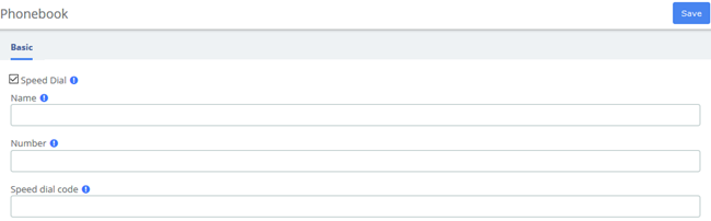
Figure 3-4-3 Phonebook interface
Navigate to PBX > Call Control > Phonebook, add a speed dial number by using the following information.
Table 3-4-3 Definition of Phonebook
Item | Definition |
Speed Dial | This option must be checked |
Name | Name of the speed dial |
Number | Destination external number |
Speed dial code | A number to associate this code to the external number to dial |
To dial this speed dial number, we dial *088, where *0 is to access the speed dial system's feature and 88 is the speed dial code we entered.
Some actions that we can perform on the speed dial administration web page are as follows:
- Export in CSV: If we click on this link, we can download the current speed dial list.
- Import from CSV: We can upload a CSV file with the format: “Name”; Number; Speeddial
Navigate to PBX > Settings > Functions Code, switch the Speeddial prefix to Enabled.
3.4.4 DISA
DISA (Direct Inward System Access) allows you to dial in from outside to the Asterisk switch (PBX) to obtain an "internal" system dial tone. You can place calls from it as if they were placed from within.
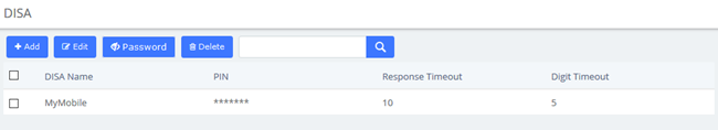
Figure 3-4-4 DISA Interface
When you choose the DISA option to call a number, you will be greeted with “Please enter your password followed by the pound key” and after entering your password, you will then get a dial tone. You may start dialing the telephone number.
Table 3-4-4 Definition of add DISA
Item | Definition |
DISA name | Give this DISA a brief name to help you identify it. |
PIN | The user will be prompted for this number. If you wish to have multiple PIN’s, separate them with commas. |
Response Timeout | The maximum amount of time it will before hanging up if the user has dialed an incomplete or invalid number. Default of 10 seconds. |
Digit Timeout | The maximum amount of time permitted between digits when the user is typing in an extension. Default of 5. |
Require Confirmation | Require Confirmation before prompting for password. Used when your PSTN connection appears to answer the call immediately. |
Caller ID | (Optional) When using this DISA, the users CallerID will be set to this. Format is “User Name” <5551234> |
Context | (Experts Only) Set the context that calls will originate from. Leaving this as from-internal unless you know what you’re doing. |
Allow Hangup | Allow the current call to be disconnected and dial tone presented for a new call by pressing the Handup feature code: ** while in a call. |
Caller ID Override | Determine if we keep the Caller ID being presented or if we override it. Default is Enable. |
3.4.5 Conference
The Conference option is used to create a single extension number that your users can dial so that they can talk to each other in a conference call. It also creates a destination to which you can send calls so that they can participate in the conference call.
For example, you could create a Conference that will allow your local phones to dial 800, and then enter into a conference call.

Figure 3-4-5 Conference interface
Below a description of each parameter:
Table 3-4-5 Definition of add Conference
Item | Definition |
Basic | |
Conference Number | Use this number to dial into the conference. |
Conference Name | Give this conference a brief name to help you identify it. |
User PIN | You can require callers to enter a password before they can enter this conference. This setting is optional. If either PIN is entered, the user will be prompted to enter a PIN. |
Admin PIN | Enter a PIN number for the admin user. This setting is optional unless the ‘leader wait’ option is in use, then this PIN will identify the leader. |
Advanced | |
Join Message | Message to be played to the caller before joining the conference. To add additional recordings use the “System Recordings” MENU to the left |
Leader Wait | Wait until the conference leader (admin user) arrives before starting the conference |
Talker Optimization | Turn on talker optimization. With talker optimization, Asterisk treats talkers who are not speaking as being muted, meaning that no encoding is done on transmission and that received audio that is not registered as talking is omitted, causing no buildup in background noise. |
Talker Detection | Sets talker detection. Asterisk will sends events on the Manager Interface identifying the channel that is talking. The talker will also be identified on the output of the meetme list CLT command. |
Quiet Mode | Quiet mode (do not play enter/leave sounds) |
User Count | Announce user(s) count on joining conference |
User join/leave | Announce user join/leave |
Music on Hold | Enable Music on Hold when the conference has single caller |
Music on Hold Class | Music (or Commercial) played to the caller while they wait line for the conference to start. Choose “inherit” if you want the MoH class to be what is currently selected, such as by the inbound route. This music is defined in the “Music on Hold” to the left. |
Allow Menu | Present Menu (user or admin) when ‘*’ is received (‘send’ to menu). |
Record Conference | Record the conference call |
Maximum Participants | Maximum Number of users allowed to join this conference. |
Mute on Join | Mute everyone when they initially join the conference. Please note that if you do not have ‘Leader Wait’ set to yes you must have ‘Allow Menu’ set to Yes to unmute yourself. |
3.4.6 Callback
Callback is where you make a call to your IP-PBX and when reached you will be disconnected, but it does not end there. Your PBX will in turn call your mobile and reconnect you relieving you of the cost of the lengthy Mobile phone call that you will otherwise be up for.
Let’s take this step by step.
1.Setup DISA
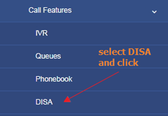

Figure 3-4-6 Set on DISA
- DISA name: MyMobile
- Response Timeout:10
- Digit Timeout:5
- Caller ID:0400123456 (My Mobile Number)
- Context: from-internal
2.Setup Callback
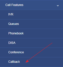
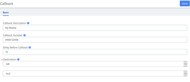
Figure 3-4-7 Callback interface
- Callback Description: My Mobile
- Callback Number: 0400123456 (My mobile Number)
- Delay Before Callback:10
- Destination after Callback: IVR – Residence (or Office IVR)
3.Inbound Routes
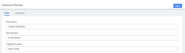
Figure 3-4-8 Inbound Routes interface
- Description: Callback-MyMobile
- DID Number:61247324100 (My DID number)
- Caller ID Number: 0400123456 (My mobile Number)
- Set Destination to: Callback – MyMobile
Click Save button then Click on the red circle at the top & follow on screen prompts

Now enable send caller ID on your mobile and call your DID number. When connected you will get one beep and then followed by silence. Hang up your mobile and wait for approximately10 seconds and your mobile will ring.
When you answer your mobile, you will hear your IVR playing with the various options. One of the silent options in my IVR is DISA. If I need to make an external call using my PBX. If I know the option and select it, I will be then get DISA where I can make an external call at no cost to my Mobile.
Table 3-4-6 Definition of add Callback
Item | Definition |
Callback Description | Enter a description for this callback |
Callback Number | Optional: Enter the number to dial for the callback. Leave this blank to just dial the incoming CallerID Number. |
Delay Before Callback | Optional: Enter the number of seconds the system should wait before calling back. |
Destination | Destination of a callback. |
Item | Definition |
Callback Description | Enter a description for this callback |
Callback Number | Optional: Enter the number to dial for the callback. Leave this blank to just dial the incoming CallerID Number. |
Delay Before Callback | Optional: Enter the number of seconds the system should wait before calling back. |
3.4.7 Parking Lot
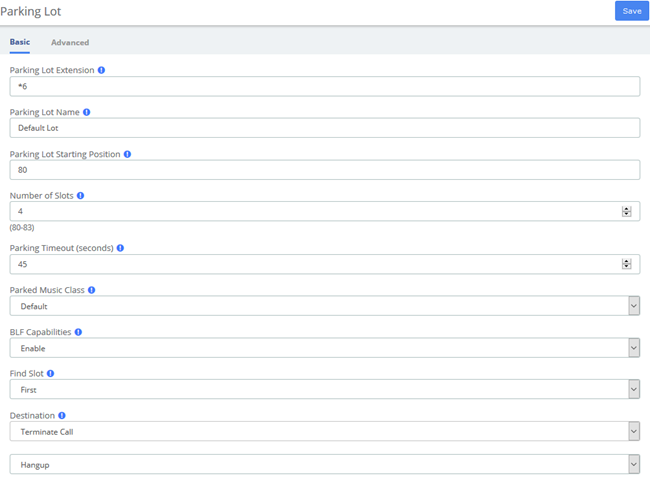
Figure 3-4-9 Parking Lot interface
Table 3-4-7 Definition of Parking Lot
Item | Definition |
Basic | |
Parking Lot Extension | This is the extension where you will transfer a call to park it |
Parking Lot Name | Name of the parking Lot. |
Parking Lot Starting Position | The starting postion of the parking lot. |
Number of Slots | The total number of parking lot spaces to configure. |
Parking Timeout (seconds) | The timeout period in seconds that a parked call will attempt to ring back the original parker if not answered. |
Parked Music Class | This is the music class that will be played to a parked call while in the parking lot UNLESS the call flow prior to parking the call explicitly set a different music class |
BLF Capabilities | Enable this to have Asterisk “hints” generated to use with BLF buttons. |
Find Slot | If you want the parking lot to seek the next sequential parking slot relative to the the last parked call instead of seeking the first available slot. |
Destination | Destination of Parking Lot. |
Advanced | |
Pickup Courtesy Tone | Whom to play the courtesy tone to when a parked call is retrieved. |
CallerID Prepend | String to prepend to the current Caller ID associated with the parked call prior to sending back to the Originator or the Alternate Destination. |
Transfer Capability | parkedcalltransfers. Enables or disables DTMF based transfers when picking up a parked call. |
Parking Alert-Info | Alert-Info to add to the call prior to sending back to the Originator or to the Alternate Destination. |
Re-Parking Capability | parkedcallreparking. Enables or disables DTMF based parking when picking up a parked call |
Auto CallerID Prepend | These options will be appended after CallerID Prepend if set. |
Announcement | Optional message to be played to the call prior to send back to the originator. |
Come Back to Origin | Where to send a parked call that has timed out. If set to yes then the parked call will be sent back to the originating device that sent the call to this parking lot. |
This module is used to configure Parking Lot(s) in Asterisk.
Simply transfer the call to said parking lot extension. Asterisk will then read back the parking lot number the call has been placed in. To retrieve the call simply dial that number back.
Table 3-4-8 Example usage of Parking Lot
*2nn: | Attended Transfer call into Park lot nnn (It will announce the slot back to you) |
nn: | Park Yourself into Parking lot nnn (Announcing your parked slot to you) |
3.4.8 Voicemail Blasting
Voicemail blasting lets you send a voicemail message to multiple users at the same time. The Voicemail Blasting module is used to create a group of users and assign a number to the group. A user can dial this number to leave a voicemail message for the group. All members of the group will receive the message in their voicemail boxes.
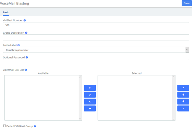
Figure 3-4-10 Voicemail Blasting interface
Table 3-4-9 Definition of add VMBlast Group
Item | Definition |
VMBlast Number | The number users will dial to voicemail boxes in this VMBlast group |
Group Description | Provide a descriptive title for this VMBlast Group. |
Audio Label | Paly this message to the caller so they can confirm they have dialed the proper voice mail group number, or have the system simply read the group number. |
Optional Password | You can optionally include a password to authenticate before providing access to this group voicemail list. |
Voicemail Box List | Select voice mail boxes to add to this group. Use Ctrl key to select multiple. |
Default VMBlast Group | Each PBX system cam have a single Default VOICEMAIL Blast Group. If specified, extensions can be automatically added (or removed) from this default group in the Extensions (or Users) tab. Making this group the default will uncheck the option from the current default group if specified. |
3.4.9 Paging and Intercom
The Paging and Intercom module is used to set up an extension number that your users can dial in order to place an intercom call to multiple phones on your system at the same time.
For example, in a small office, you might set up a page group with extension number "100." When 100 is dialed by a local user, all of the phones in the office would go off-hook, and you could speak to everyone at every extension at the same time. Alternatively, you could set up page groups with different extension numbers for each department in the office, i.e. 100 for sales, 110 for service, and so on.
This module is for specific phones that are capable of Paging or Intercom. This section is for configuring group paging, intercom is configured through Feature Codes. Intercom must be enabled on a handset before it will allow incoming calls. It is possible to restrict incoming intercom calls to specific extensions only, or to allow intercom calls from all extensions but explicitly deny from specific extensions.
This module should work with Aastra, Grandstream, Linksys/Sipura, Mitel, Polycom, SNOM, and possibly other SIP phones (not ATAs). Any phone that is always set to auto-answer should also work (such as the console extension if configured). Intercom mode is currently disabled, it can be enabled in the Feature Codes Panel.
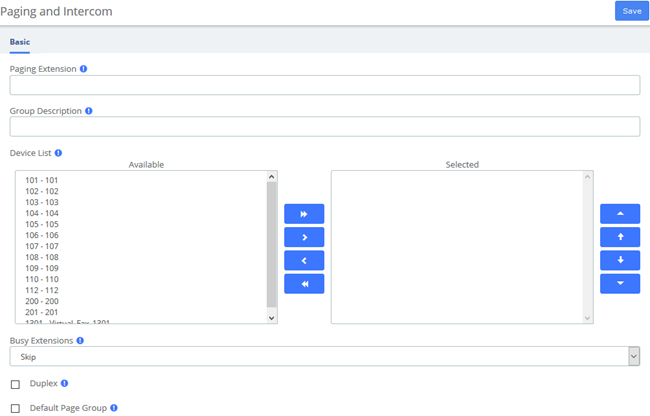
Figure 3-4-11 Paging and Intercom interface
Table 3-4-10 Definition of Paging and Intercom
Item | Definition |
Paging Extension | The number users will dial to page this group. |
Group Description | Provide a descriptive title for this VMBlast Group. |
Device List | Choose extensions. |
Busy Extensions | Skip will not page any busy extension. All other extensions will be paged as normal Force will not check if the device is in use before paging it. This means conversations can be interrupted by a page (depending on how the device handles it). |
Duplex | Paging is typically one way for announcements only Checking this will make the paging duplex, allowing all phones in the paging group to be able to talk and be heard by all. |
3.4.10 Scheduled Broadcast
You can broadcast some audio by setting up the scheduled broadcast feature to inform the group.
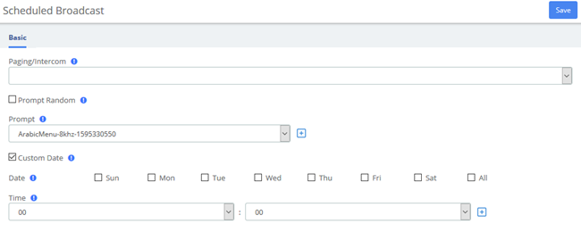
Figure 3-4-12 Scheduled Broadcast interface
Table 3-4-11 Definition of Scheduled Broadcast
Item | Definition |
Paging/Intercom | Select the desired paging group or intercom group. |
Prompt Random | If enabled, the prompt should be played randomly. |
Prompt | Select the desired prompt. |
Custom Date | You can select a time to play the scheduled broadcast on a special day. |
3.4.11 Wakeup Service
User can enable the Wakeup service and set the time and date, members, and receive the call reminder after the time. The wake-up service will ring for 30 seconds every 30 seconds for the duration of the wake-up service.
In the following example, the wakeup service is set up for extension101-110 from Monday to Friday on 7:40AM.
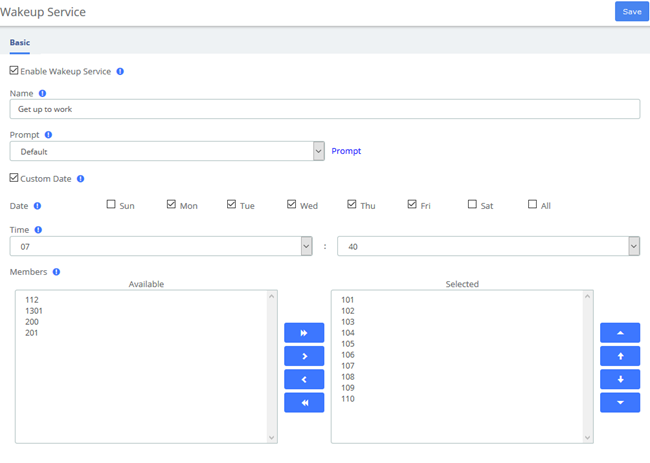
Figure 3-4-13 Wakeup Service Interface
3.5 Voice Prompts
3.5.1 Languages
The Languages module is used to allow calls to be routed to localized or alternate language recordings.
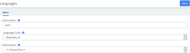
Figure 3-5-1 Languages interface
Languages allow you to change the language of the call flow and then continue on to the desired destination. For example, you may have an IVR option that says "For French Press 5 now". You would then create a French language instance and point it's destination at a French IVR. The language of the call's channel will now be in French. This will result in French sounds being chosen if installed.
Table 3-5-1 Definition of add Language
Item | Definition |
Description | The descriptive name of this language instance. For example, “French Main IVR” |
Language Code | The Asterisk language code you want to change to. For example, “fr” for French. |
Destination | Indicates extension, Ring Group, Voicemail or other destination to which the call is supposed to be directed when the outside callers have called specified |
3.5.2 System Recordings
The System Recordings module is used to record or upload messages that can then be played back to callers in other modules. It can also be used to make pre-installed Asterisk recordings available for use in other modules.
For example, you might create a recording called "Main Menu" and then play that message in an IVR before a caller is asked to make a selection. Or, you might record a recording called "Holiday Message" and then use that message in an Announcement. You would then route incoming calls to the Announcement or IVR using the Inbound Routes Module.
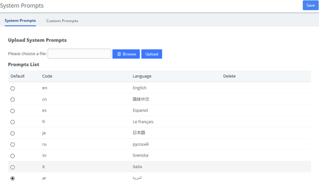
Figure 3-5-2 System Recordings interface
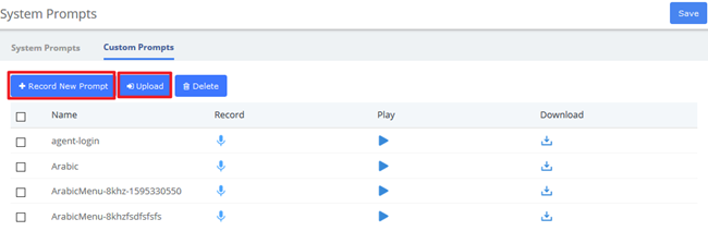
Figure 3-5-3 Custom Prompts Interface
3.5.3 Announcement
The Announcements Module is used to create a destination that will play an informational message to a caller. After the message is played, the call will proceed to another destination.
For example, you might create an Announcement that plays the address, fax number, and the web-site of your business. A caller could reach that message by pressing the number 2 from the company's main menu. After hearing the message, the call might be routed back to the company's main menu and allowed to make another selection.

Figure 3-5-4 Announcements interface
Table 3-5-2 Definition of Announcements
Item | Definition |
Name | The name of this announcement |
Recording | Message to be played. To add additional recordings, use the “System Recordings” MENU to the left |
Repeat | Key to press that will allow for the message to be replayed. If you choose this option there will be a short delay inserted after the message. If a longer delay is needed it should be incorporated into the recording. |
Allow Skip | If the caller is allowed to press a key to skip the message |
Return to IVR | If the announcement came from an IVR and this box is checked, the destination below will be ignored and instead it will be return to the calling IVR. Otherwise, the destination below will be taken. Don’t check if not using in this mode. The IVR return location will be to the last IVR in the call chain that was called so be careful to only check when needed. For example, if an IVR directs a call to another destination which eventually calls this announcement and this box is checked, it will return to that IVR which may not be the expected behavior. |
Don't Answer Channel | Check this to keep the channel from explicitly being answered. When checked, the message will be played and if the channel supports that. When not checked, the channel is answered followed by a 1 second delay. When using an announcement from an IVR or other sources that have already answered the channel, that 1 second delay may not be desired. |
Destination | Indicates extension, Ring Group, Voicemail or other destination to which the call is supposed to be directed when the outside callers have called specified |
3.5.4 Route Congestion
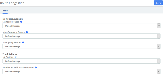
Figure 3-5-5 Route Congestion Messages interface
Table 3-5-3 Definition of Route Congestion Messages
Item | Definition |
No Routes Available | |
Standard Routes | Message or tone to be played if no trunks are available. |
Intra-Company Routes | Message or tone to be played if no trunks are available. Used on routes marked as intra-company only. |
Emergency Routes | Message or tone to be played if no trunks are available. Used on all emergency routes. Consider a message instructing caller to find an alternative means of calling emergency services such as a cell phone or alarm system panel. |
Trunk Failures | |
No Answer | Message or tone to be played if there was no answer. Default message is: “The number is not answering." Hangupcause is 18 or 19 |
Number or Address Incomplete | Message or tone to be played if trunk reports Number or Address Incomplete. Usually this means that the number you have dialed is to short. Default message is: “The number you have dialed is not in service. Please check the number and try again."Hangupcause is 28 |
3.5.5 Music On Hold
The volume adjustment is a linear value. Since loudness is logarithmic, the linear lever will be less of an adjustment. You should test out the installed music to assure it is at the correct volume. This feature will convert MP3 files to WAV files. If you do not have mpg123 installed, you can set the parameter: Convert Music Files to WAV to false in Advanced Settings.
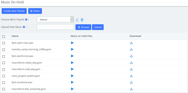
Figure 3-5-6 Music on Hold Interface
You can add a custom music on hold playlist and upload your audio files to the PBX.
1.Add a Custom music on hold Playlist.
Go to PBX > Voice Prompts > Music on Hold page, click Create New Playlist. On the configuration page, set the playlist name and the playlist order, click Save.
2.Upload the audio file.
Click Browse to choose an audio file from your local PC, and then click Upload
3.6 Settings
3.6.1 Global Settings

Figure 3-6-1 Global Settings Interface
Table 3-6-1 Instruction of Global Settings/Basic
Options | Definition |
Asterisk Manager | |
Asterisk Manager Password | Password for accessing the Asterisk Manager Interface (AMI), this will be automatically updated in manager.conf. |
Asterisk Manager User | Username for accessing the Asterisk Manager Interface (AMI), this will be automatically updated in manager.conf. |
System Setup | |
Aggressively Check for Duplicate Extensions | Aggressively Check for Duplicate Extensions |
User & Devices Mode | Sets the extension behavior in UC device. If set to extensions, Devices and Users are administered together as a unified Extension, and appear on a single page. If set to deviceanduser, Devices and Users will be administered separately. |
Call Recording Format | Format to save recoreded calls for most call recording unless specified differently in specific applications. |
Convert Music Files to WAV | When set to false, the MP3 files can be loaded and WAV files converted to MP3 in the MoH module. The default behavior of true assumes you have mpg123 loaded as well as sox and will convert MP3 files to WAV. This is highly recommended as MP3 files heavily tax the system and can cause instability on a busy phone system |
Voice Prompts | |
Default language | The default language for Voice Prompts. |
3.6.2 Analog Settings
Basic setting
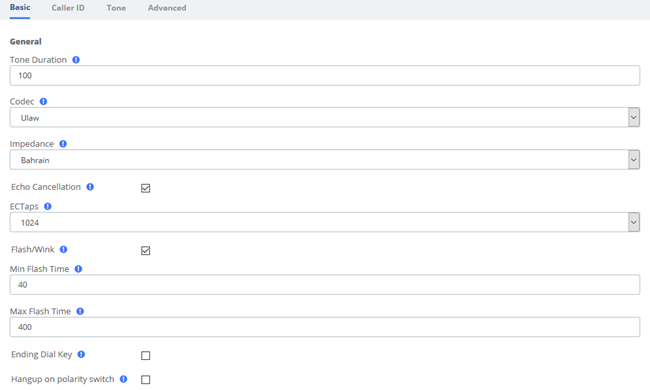
Figure 3-6-2 Analog Settings/Basic/General Configuration
Table 3-6-2 Instruction of General
Options | Definition |
Tone duration | How long generated tones (DTMF and MF) will be played on the channel. (in milliseconds) |
Codec | Set the global encoding: ulaw, alaw. |
Impedance | Configuration for impedance. |
Echo Cancellation | Enable/Disable |
EC Taps | 128/256/512/1024 |
Flash/Wink | Turn on/off Flash/wink. |
Min flash time | Min flash time. (in milliseconds). |
Max flash time | Max flash time. (in milliseconds). |
Ending Dial Key | Turn on/off Ending Dial Key (#). |
Hang up on polarity switch | Turn on/off Hangup on polarity switch |
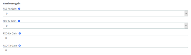
Figure 3-6-3 Analog Settings/Basic/Hardware gain
Table 3-6-3 Instruction of Analog Settings/Basic/Hardware gain
Options | Definition |
FXO Rx gain | Set the FXO port Rx gain. Range: from -150 to 120. |
FXO Tx gain | Set the FXO port Tx gain. Range: from -150 to 120. |
FXS Rx gain | Set the FXS port Rx gain. Range: -35, 0 or 35. |
FXS Tx gain | Set the FXS port Tx gain. Range: -35, 0 or 35. |
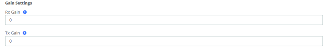
Figure 3-6-4 Analog Settings/Basic/Gain Settings
Table 3-6-4 Instruction of Analog Settings/Basic/Gain
Options | Definition |
Rx gain | Gain for the rx (receive) channel. Default: 0.0 |
Tx gain | Gain for the tx (transmit) channel. Default: 0.0 |
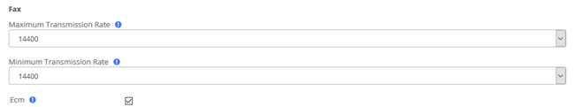
Figure 3-6-5 Analog Settings/Basic/Fax
Table 3-6-5 Definition of Analog Settings/Basic/Fax
Options | Definition |
Maximum Transmission Rate | Set the maximum transmission rate |
Minimum Transmission Rate | Set the minimum transmission rate |
Ecm | Enable/disable T.30 ECM (error correction mode) by default. |
Caller ID setting
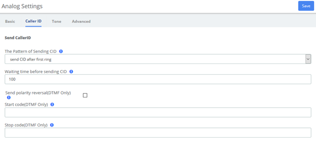
Figure 3-6-6 Analog Settings/Caller ID/Send Caller ID
Table 3-6-6 Instruction of Analog Settings/Caller ID/Send Caller ID
Option | Description |
The pattern of sending CID | Some countries (UK) have ring tones with different ring tones(ring-ring), which means the caller ID needs to be set later on, and not just after the first ring, as per the default (1). |
Waiting time before sending CID | How long we will be waiting before sending the CID on the channel. (in milliseconds). |
Sending polarity reversal (DTMF Only) | Send polarity reversal before sending the CID on the channel. |
Start code (DTMF Only) | Start code. |
Stop code (DTMF Only) | Stop code. |
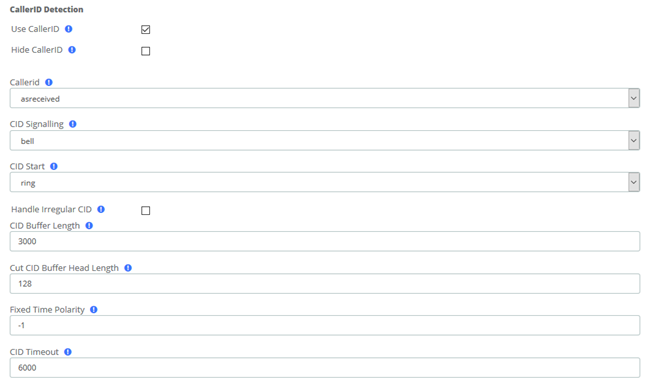
Figure 3-6-7 Analog Settings/Caller ID/CallerID Detection
Table 3-6-7 Instruction of Analog Settings/Caller ID/CallerID detect
Options | Definition |
Use CallerID | Turn on/off CallerID detect function |
Hide CallerID | Turn on/off CallerID detect function |
Callerid | Caller ID can be set to "asreceived" or a specific number if you want to override it. Note that "asreceived" only applies to trunk interfaces. |
CID Signalling | Type of caller ID signalling in usebell = bell202 as used in US (default)v23 = v23 as used in the UKdtmf = DTMF as used in Denmark, Sweden and Netherlands |
CID Start | What signals the start of caller IDring=a ring signals the start (default) polarity=polarity reversal signals the start |
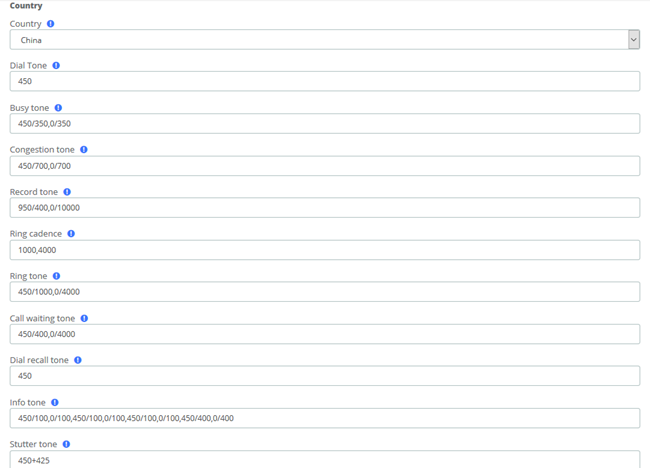
Figure 3-6-8 Analog Settings/Tone/Country
Table 3-6-8 Definition of Analog Settings/Tone/Country
Options | Definition |
Country | Configuration for location specific tone indications. |
Dial tone | Set of tones to be played when one picks up the hook. |
Busy tone | Set of tones played when the receiving end is busy. |
Congestion tone | Set of tones played when there is some congestion. |
Record tone | Set of tones played when call recording is in progress. |
Ring cadence | List of durations the physical bell rings. |
Ring tone | Set of tones to be played when the receiving end is ringing. |
Call waiting tone | Set of tones played when there is a call waiting in the background. |
Dial recall tone | Many phone systems play a recall dial tone after hook flash. |
Info tone | Set of tones played with special information messages (e.g., number is out of service.) |
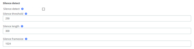
Figure 3-6-9 Analog Settings/Tone/Silence detect
Table 3-6-9 Definition of Analog Settings/Tone/Silence detect
Options | Definition | |
Silence detect | Turn on/off silence detect function | |
Silence threshold | What we consider silence: the lower, the more sensitive, eg:250 is 250ms. Range: 100 to 500(100 to 500ms), default: 250 | |
Silence length | How many silence threshold of silence before hanging up(eg: 16 is 250ms*16=4s). Range: 2 to 1020 (200ms to 512s), default: 80(20s) | |
Silence framesize | Rx threshold | Range: -20 dBm0 to -40 dBm0, default: 20(-20 dBm0), all values are understood to be negative. |
Tx threshold | Range: -20 dBm0 to -40 dBm0, default: 20(-20 dBm0), all values are understood to be negative. | |

Figure 3-6-10 Analog Settings/Tone/Special tone
Table 3-6-10 Instruction of Analog Settings/Tone/Special tone
Options | Definition |
Custom Busy Tone detect | Turn on/off busy detect function |
Busy Tone count | How many busy tones to wait for before hanging up. The default is 3, but it might be safer to set to 6 or even 8. |
Busy Tone pattern | Set the busy detect country |
3.6.3 SIP Settings
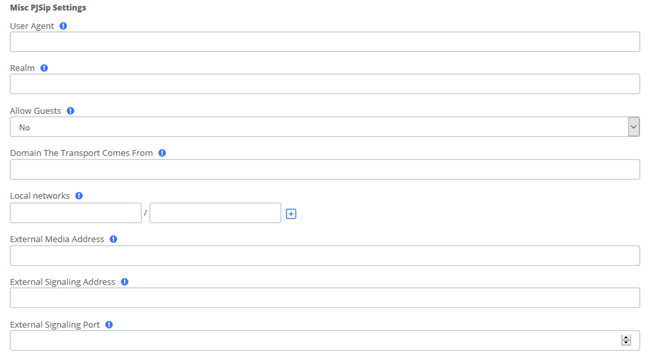
Figure 3-6-11 SIP Settings/Basic/Misc PJSip Settings
Table 3-6-11 Instruction of SIP Settings/Basic/Misc PJSip Settings
Options | Definition |
User Agent | Value used in User-Agent header for SIP requests and Server header for SIP responses. |
Realm | When generates a challenge, the digest realm will be set to this value if there is no better option (such as auth/realm) to be used. |
Allow Guests | When set Asterisk will allow Guest SIP calls and send them to the Default SIP context. Turning this off will keep anonymous SIP calls from entering the system. Doing such will also stop 'Allow Anonymous Inbound SIP Calls' from functioning. Allowing guest calls but rejecting the Anonymous SIP calls below will enable you to see the call attempts and debug incoming calls that may be mis-configured and appearing as guests. |
Domain The Transport Comes From | Typically used with SIP calling. Example user@domain, where domain is the value that would be entered here |
Local networks | Local network settings in the form of ip/cidr or ip/netmask. For networks with more than 1 LAN subnets, use the Add Local Network Field button for more fields. Blank fields will be ignored. |
External Media Address | External IP address to use in RTP handling. |
External Signaling Address | External address for SIP signaling. |
External Signaling Port | External port for SIP signaling. |
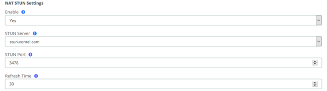
Figure 3-6-12 SIP Settings/Basic/NAT STUN Settings
Table 3-6-12 Instruction of SIP Settings/Basic/NAT STUN Settings
Options | Definition |
Enable | If enabled, the Nat Stun will be enabled. |
STUN Server | Address of the STUN server to query. Custom valid form:[(hostname | IP-address)] |
STUN Port | The port defaults to the standard STUN port (3478). |
Refresh Time | Number of seconds between STUN refreshes, Default is 30. |
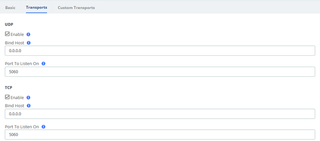
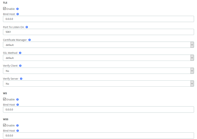
Figure 3-6-13 SIP Settings/Transports
Table 3-6-13 Instruction of SIP Settings/Transports
Options | Definition |
UDP | |
Enable | USE 0.0.0.0 - All |
Bind Host | You can customize the UDP bind host, the default is 0.0.0.0 |
Port To Listen On | The port that this transport should listen on |
TCP | |
Bind Host | You can customize the TCP bind host, the default is 0.0.0.0 |
Port To Listen On | The port that this transport should listen on |
TLS | |
Bind Host | You can customize the TLS bind host, the default is 0.0.0.0 |
Port To Listen On | The port that this transport should listen on |
Certificate Manager | Select a certificate to use for the TLS transport. These are configured in the module Certificate Manager1 |
SSL Method | Method of SSL transport (TLS ONLY). The default is currently TLSv1, but may change with future releases.1 |
Verify Client | Require verification of server certificate (TLS ONLY). |
Verify Server | Require verification of server certificate (TLS ONLY). |
WS | |
Bind Host | You can customize the WS bind host, the default is 0.0.0.0 |
WSS | |
Bind Host | You can customize the WSS bind host, the default is 0.0.0.0 |
3.6.4 IAX2 Settings
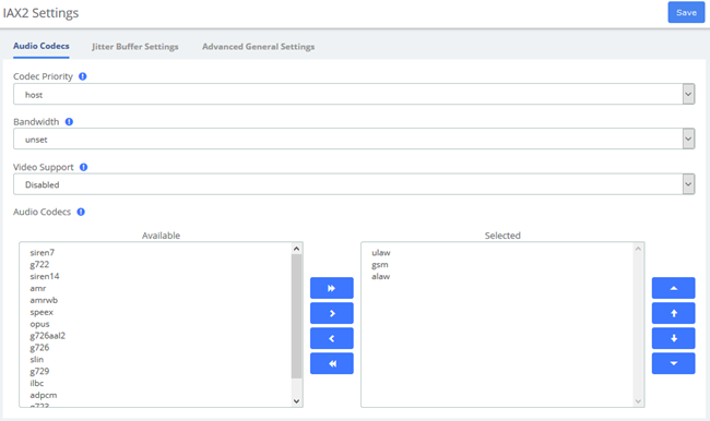
Figure 3-6-14 IAX2 Settings/Audio Codecs
Table 3-6-14 Instruction of IAX2 Settings/Audio Codecs
Options | Definition |
Codec Priority | Asterisk: codecpriority. Controls the codec negotiation of an inbound IAX call. This option is inherited to all user entities. It can also be defined in each user entity separately which will override the setting here. The valid values are:host - Consider the host's preferred order ahead of the caller's.caller - consider callers host's. disabled disable consideration codec preference altogether. (this is original behavior before preferences were added)reqonly same as disabled, only do not capabilities if requested format available call will be accepted available. |
Bandwidth | Asterisk: bandwidth. Specify bandwidth of low, medium, or high to control which codecs are used in general. |
Video Support | Check to enable and then choose allowed codecs. If you clear each codec and then add them one at a time, submitting with each addition, they will be added in order which will effect the codec priority. |
Audio Codecs | Check the desired codecs, all others will be disabled unless explicitly enabled in a device or trunks configuration. Drag to re-order. |
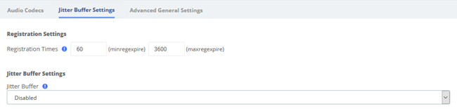
Figure 3-6-15 IAX2 Settings/Jitter Buffer Settings
Table 3-6-15 Instruction of IAX2 Settings/Jitter Buffer Settings
Options | Definition |
Registration Settings | |
Registration Times | Asterisk: minregexpire, maxregexpire. Minimum and maximum length of time that IAX peers can request as a registration expiration interval (in seconds). |
Jitter Buffer Settings | |
Jitter Buffer | Asterisk: jitterbuffer. You can adjust several parameters relating to the jitter buffer. The jitter buffer’ s function is to compensate for varying network delay. the jitter buffer works incoming audio - outbound will be dejittered by at other end. |
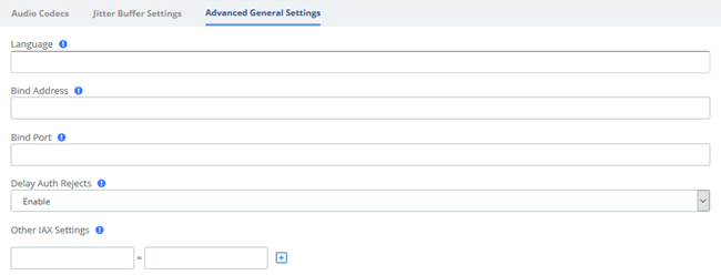
Figure 3-6-16 IAX2 Settings/Advanced General Settings
Table 3-6-16 Instruction of IAX2 Settings/Advanced General Settings
Options | Definition |
Language | Default Language for a channel, Asterisk: language |
Bind Address | Asterisk: bindaddr. The IP address to bind to and listen for calls on the Bind Port. If set to 0.0.0.0 Asterisk will listen on all addresses. To bind to multiple IP addresses or ports, use the Other iax settings' fields where you can put settings such as:bindaddr='192.168.10.100:4555.' it is recommended to leave this blank. |
Bind Port | Asterisk: bindport. Local incoming UDP Port that Asterisk will bind to and listen for IAX messages. The IAX standard is 4569 and in most cases this is what you want. It is recommended to leave this blank. |
Delay Auth Rejects | Asterisk: delayreject. For increased security against brute force password attacks enable this which will delay the sending of authentication reject for REGREQ or AUTHREP if there is a password. |
Other IAX Settings | You may set any other IAX settings not present here that are allowed to be configured in the General section of iax.conf. There will be no error checking against these settings so check them carefully. They should be entered as: [setting] = [value]in the boxes below. Click the Add Field box to add additional fields. Blank boxes will be deleted when submitted. |
3.6.5 RTP Settings
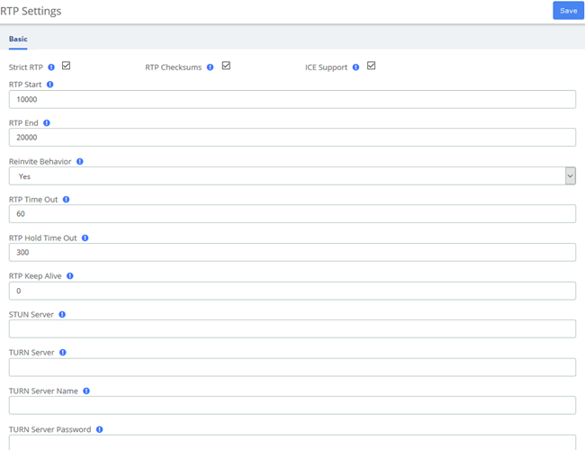
Figure 3-6-17 RTP Settings
Table 3-6-17 Definition of RTP Settings Options
Options | Definition |
Strict RTP | Enable strict RTP protection. This will drop RTP packets that do not come from the source of the RTP stream. This option is disabled by default. |
RTP Checksums | Whether to enable or disable UDP checksums on RTP traffic |
ICE Support | Whether to enable ICE support. Defaults to no. ICE (Interactive Connectivity Establishment) is a protocol for network address Translator (NAT) traversal for UDP-based multimedia sessions established with the offer/answer model. This option is commonly enabled in WebRTC setups |
RTP Start | Start of range of port numbers to be used for RTP. Defaults is 10000. |
RTP End | End of range of port numbers to be used for RTP. Defaults is 20000. |
Reinvite Behavior | yes: standard reinvites; (yes = update + nonat) no: never; nonat: An additional option is to allow media path redirection (reinvite) but only when the peer where the media is being sent is known to not be behind a NAT (as the RTP core can determine it based on the apparent IP address the media arrives from; update: use UPDATE for media path redirection, instead of INVITE. |
RTP Time Out | The call is terminated when there is no RTP or RTCP activity on the audio channel for a period of time (that is, the set timeout period). This is to be able to hang up the call in case of network interruption (not on hold) |
RTP Hold Time Out | If there is no RTP or RTCP activity on the audio channel for a period of time (that is, the set hold timeout period), the call will be terminated (in hold state). This value must be greater than the timeout period. |
RTP Keep Alive | Send Keepalive in RTP stream to keep NAT open (default is off) |
STUN Server | Configure the STUN server address. STUN is a Client/Server protocol and also a Request/Response protocol. It is used here to check the connectivity between two terminals, like a way to maintain NAT binding entries Keep-alive agreement. |
TURN Server | Configure the TURN server address, STUN can handle most of the NAT problems. TURN is an enhanced version of the STUN protocol, dedicated to dealing with symmetric NAT problems. |
TURN Server Name | Configure the TURN Server name |
TURN Server Password | Configure the TURN Server password |
3.6.6 Recording Settings
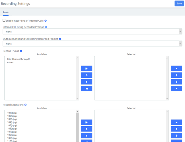
Figure 3-6-18 Recording Settings
Table 3-6-18 Definition of Recording Settings Options
Options | Definition |
Enable Recording of Internal Calls | Check this option, and all internal calls made by the selected extensions will be recorded automatically. |
Internal Call Being Recorded Prompt | If the internal call has enabled call recording, this prompt will notify the called party that the call is being recorded. |
Outbound/Inbound Calls Being Recorded Prompt | If the external call (outbound/inbound) has enabled call recording, this prompt will notify the external party that the call is being recorded. |
Record Trunks | When a call reaches the selected trunk, it will be recorded. |
Record Extensions | The selected extensions will be recorded. |
Record Conferences | The selected conferences will be recorded. |
3.6.6 Misc Destinations
The Misc Destinations Module is used to create a miscellaneous destination to which you can route calls from another module.
For example, you might create a misc destination called "My Mobile Phone" that dials your mobile telephone number. Then, you could set up an IVR so that if a caller presses 9, they would be routed to "Misc Destinations:My Mobile Phone."
Misc Destinations are for adding destinations that can be used by other FreePBX modules, generally used to route incoming calls. If you want to create feature codes that can be dialed by internal users and go to various destinations, please see the Misc Applications module. If you need access to a Feature Code, such as *98 to dial voicemail or a Time Condition toggle, these destinations are now provided as Feature Code Admin destinations. For upgrade compatibility, if you previously had configured such a destination, it will still work but the Feature Code short cuts select list is not longer provided.

Figure 3-6-19 Misc Destinations interface
Table 3-6-19 Definition of add Misc Destination
Item | Definition |
Description | Give this Misc Destination a brief name to help you identify it. |
Dial | Enter the number this destination will simulate dialing, exactly as you would dial it from an internal phone. When you route a call to this destination, it will be as if the caller dialed this number from an internal phone. |
3.6.7 Functions Code
The Feature Codes Module is used to enable and disable certain features available in your PBX and Asterisk, and to set the codes that local users will dial on their phones to use that particular feature.
For example, the Feature Codes Module can be used to set the code that a user will dial to activate or deactivate Call Forwarding. It can also be used to set a Code that can be used to enter into an Echo Test, to hear your extension number, or to hear the time of day.
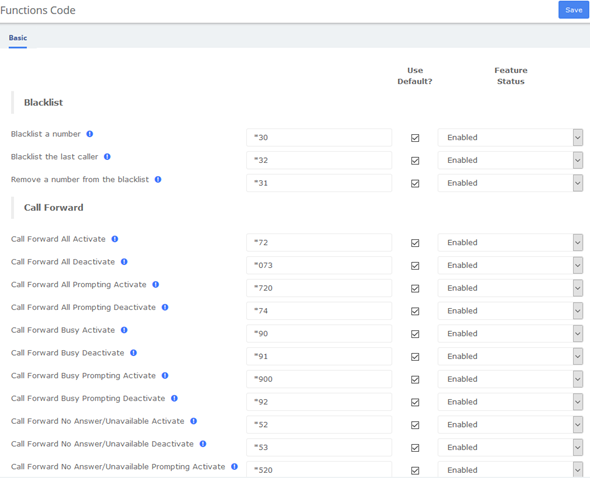
Figure 3-6-20 Feature code admin interface
3.6.8 AMI
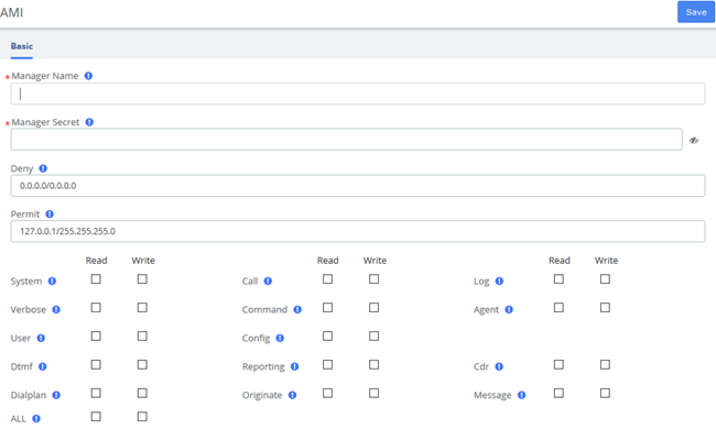
Figure 3-6-21 Manager User interface
Table 3-6-20 Definition of Manager User
Item | Definition |
Manager name | Name of the manager without space. |
Manager secret | Password for the manager. |
Deny | If you want to deny many hosts or networks, use & char as separator. Example: 192.168.1.0/255.255.255.0&10.0.0.0/255.0.0.0 |
Permit | If you want to permit many hosts or networks, use & char as separator. Look at deny example. |

Figure 3-6-22 AMI Setting interface
Table 3-6-21 Definition of AMI Setting Options
Item | Definition |
AMI Port | Sets the port number to listen on for AMI connections. Port numbers can not be less than 1024. The default is 7777. |
TLS Enable | Enables listening for AMI connections using TLS. The default is no. |
TLS Port | Sets the port to listen on for TLS connections to the AMI. The default is 5039. |
TLS Bind Address | Sets the address to listen on for TLS-based AMI connections. The default is to listen on all addresses (0.0.0.0). |
Timestamp Events | Add a Unix epoch timestamp to events (but not action responses. |
Write Timeout | Write Timeout |
3.7 Recording
3.7.1 Call Recordings
The option "Calls Recordings" of the Menu "Recordings" in UC series lets us view a list with details of all recorded calls for the extension associated to the connected user. The administrator account can see all the recordings.

Figure 3-7-1 Calls Recordings interface
3.7.2 VoiceMails
The option "Voicemail" of the Menu “Recordings” in UC series lets us view a list with details of the voicemails for the extension of the logged user.
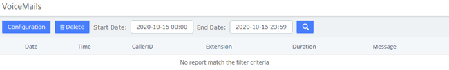
Figure 3-7-2 Voicemails interface
The report will change depending on the values of the filter:
Table 3-7-1 Definition of Show Filter
Parameter | Description |
Start Date | Start date for the selection of voicemails. |
End Date | End date for the selection of voicemails. |
To delete a voicemail, just select the voicemail from the list and click on "Delete" button.
3.7.3 VoiceMails Admin
The option "Voicemail Admin" of the Menu “Recordings” lets us view or modify some voicemail configuration.
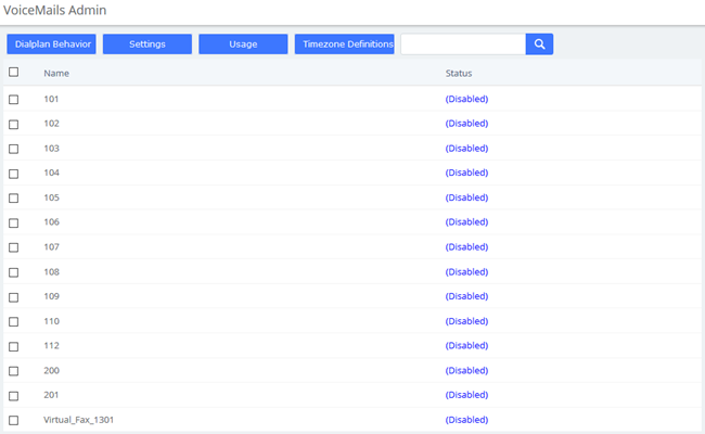
Figure 3-7-3 Voicemails Admin interface
3.8 Tools
3.8.1 Asterisk-Cli
The option “Asterisk-Cli” of the Menu “Tools” in UC series lets us execute Asterisk commands.
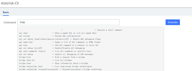
Figure 3-8-1 Asterisk-Cli interface
To execute a command, input the same in the Command field and click on the Execute button.
The module "Asterisk File Editor" of the Menu "Tools" in UC series lets us edit easily the configuration files of UC series, while you have to enter the developer mode before use it. The path of the files you can modify is /etc/asterisk/.
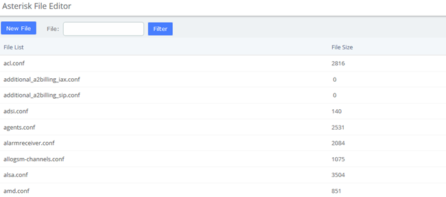
Figure 3-8-2 Asterisk File Editor interface
Editing a file
You can find a file by entering the name in the filter field. To edit the file, click on the name to go to the edit mode. Click on "Save" button to save changes and "Reload Asterisk" if necessary.
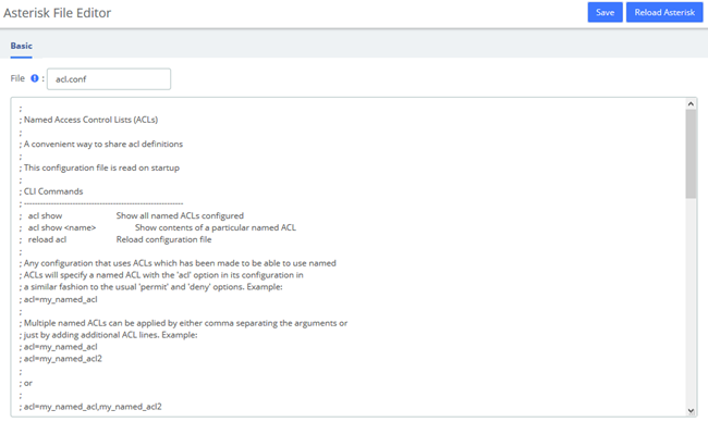
Figure 3-8-3 Editing a file interface
Creating a file
Also you can create a new file by clicking on "New File" button. This file will be created with the extension ".conf" in /etc/asterisk/.
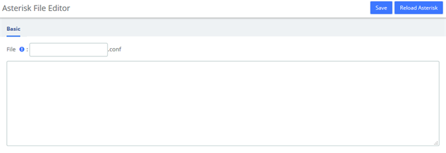
Figure 3-8-4 Create a file interface
3.8.2 AI TTS
Text can be converted to audio in the "AI TTS" function module. The output format of this file can be ".wav". Write the information you want to convert, select the output format, and click the "Generate Audio File" button. The system will automatically save the file to the location of your hard drive as you requested.
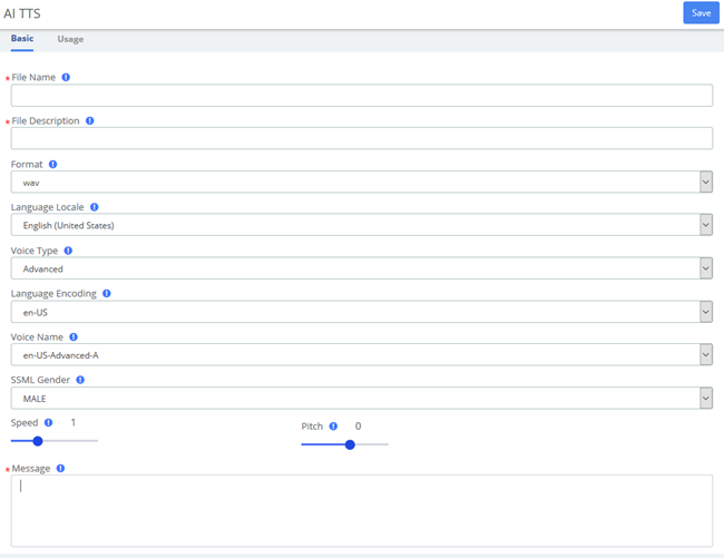
Figure 3-8-5 Text to Wav interface
3.8.3 API
This VoIP PBX provides the API interfaces for you to integrate a third-party software or device. You need enable API to access on the pbx and Set the Username and Password, click Save and Apply. The 3rd-party software should use the user name and the password to connect to the PBX API.

Figure 3-8-6 API Interface
In Extension tab, you can set whether to monitor extension status.
If the extension status is changed, the PBX will send report to the 3rd-party application server.
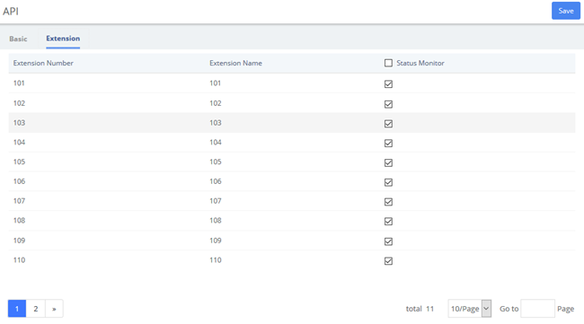
Figure 3-8-7 Extension Status Interface
3.9 Auto Provision
The "Endpoint Configurator" module enables automatic remote configuration of supported endpoints. With this module, the UC series administrator can point supported endpoints to the UC series as their telephony server.
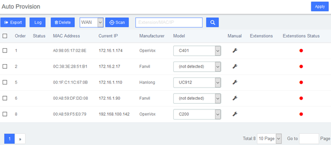
Figure 3-9-1 Endpoint Configurator interface
Interface description
Main listing
This is the listing of all endpoints that have been detected or entered. Unlike the old implementation, any endpoints detected or uploaded in past sessions will be kept and displayed until they are explicitly erased. The main listing contains the following columns:
Table 3-9-1 Description of Endpoint Configurator Interface
Item | Description |
Status | This displays the status of the endpoint as one or more icons. The available flags are as follows: Scroll icon: the endpoint has not been scanned, but rather defined in an upload. Disk icon: the endpoint configuration has been updated in the database but not yet applied to its configuration files. Person icon: the endpoint has at least one endpoint assigned. |
MAC Address | This is the main identifier for the endpoint. Configurations in the database and uploaded files are considered to refer to the same endpoint if they reference the same MAC address. |
Current IP | If the endpoint was detected through a scan, this field will show the IP at which the endpoint was found. This field is a link to the HTTP configuration interface (if supported) of the phone. |
Manufacturer | This displays the detected manufacturer of the endpoint. |
Model | This displays the detected model of the endpoint. Since automatic model detection is not (yet) implemented for some manufacturers, this field allows the user to correct the model via a drop-down list. Accurate model detection is required for many other features (such as account assignment) to work. |
Options | This link displays a modal dialog on which common options for the endpoint can be manually configured. |
 Endpoint scan toolbar button
This widget contains a textbox with a network/netmask definition, and a magnifying glass icon. By default, the network definition will be filled with the network definition of the first ethernet interface of the server. The user may correct this definition to restrict the scan, and then click on the icon to start the scan. When scanning, the toolbar will change to a spinning icon and a Cancel button. As endpoints are detected, they will be added to the main listing, along with their detected manufacturer and model. The toolbar will revert to its default state when the scan is done, or if the scan is aborted with the Cancel button.
Endpoint configuration toolbar button
Select a phone that needs to be configured, click and the following window will pop up, you can clearly see some of the phone's attributes:
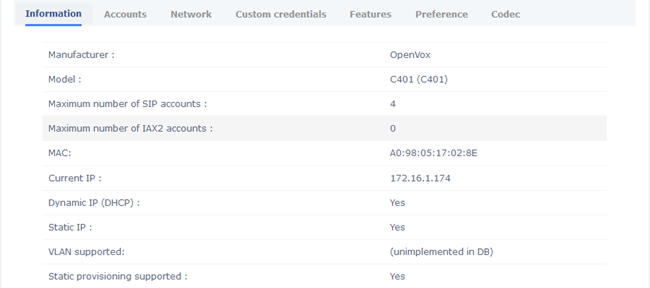
Figure 3-9-2 Endpoint Information
Click  to set the extension, and check the line 1/2/3/4 to set the line independently without affecting other lines.
You can also click  to adjust the network parameters of the phone. When selecting static IP, please make sure to manually enter IP and other parameters.
 Configuration apply toolbar button
Clicking on this button will start applying the configuration for all selected endpoints (all endpoints for which the checkbox is set). When applying the configuration, the toolbar will change to a progress bar. As endpoints are configured, the progress bar will update, and the toolbar will revert to the default state when the configuration is done. During configuration, a log is generated, and can be viewed by clicking on the Configuration Log toolbar button.
 Configuration Log toolbar button
Clicking on this button will open a modal dialog in which a log of the last configuration run will be shown. This is useful for diagnosing issues with the module failing to configure an endpoint.
 Remove configuration toolbar button
Clicking on this button will (after a confirmation dialog) remove the database records for the selected endpoints, as well as any generated configuration files for these endpoints. It will NOT, however, contact the endpoints themselves in any way.
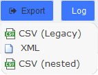 Download toolbar button
Clicking on this button will display a list of links to download the list of endpoints stored on the database, in three different formats. The supported formats are:
- CSV (Legacy). This is the format used by the old Endpoint Configurator.
- This format allows the definition of endpoints with multiple accounts and properties, as an XML document.
- CSV (Nested). This format can be generated by careful editing in a spreadsheet, and uses indentation to group multiple accounts and properties per endpoint.
3.10 PBX Monitor
The " PBX Monitor " module of the menu "PBX" in UC IPPBX allows managing the telephony operations. You can control inbound calls, outbound calls, the order in which the calls are taken, the area that is designated to attend a call, etc.
This module is useful for receptionists who have a general view of the queues, conferences, parking lots, internal extensions, trunks. Here the receptionist can start a call or transfer a call by dragging one extension to another, or include several extensions to a conference room, or a queue. The receptionist can also see the busy extensions, the elapsed time and the caller ID.
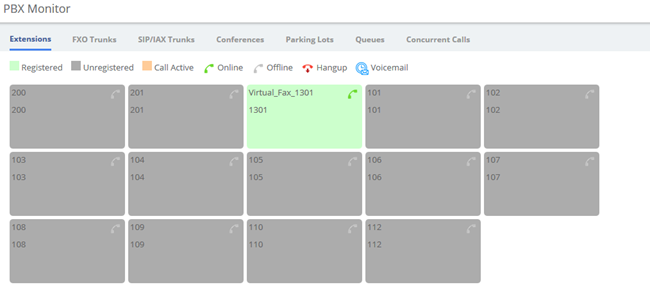
Figure 3-10-1 Operator Panel interface
Click  to forcibly hang up the calling extension.
Click  to jump to PBX>Recording>Voicemail
3.11 Conference Panel
The conference panel can help you easily manage and monitor the conference and realize multi-party calls.
3.11.1 Conference List
In the Conference List, you can check how many conferences are created on the PBX, and monitor the status of the conferences.
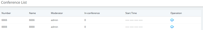
Figure 3-11-1 Conference List Interface
Click the  icon to enter the operation panel, as shown below:
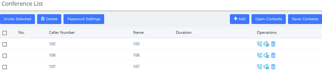
Figure 3-11-2 Conference Operation Interface
Click the  icon to invite the extension into the conference room. Of course, you can also select multiple extensions and click one key to invite the selected extensions. In addition, extensions can also directly dial the conference room number to actively join the conference room.
Click the  icon to kick the extension out of the conference room.
Click the  icon, the extension will be muted, and other extensions will not hear the sound of this extension.
Click the  icon, the extension will be unmuted, and other extensions can hear the voice of this extension.
Click the  icon to delete the extension from the conference operation panel. Of course, you can also select multiple extensions and
  the selected extension with one click.
Click  to change the password of the participant (non-administrator). Leave it blank to indicate that no password is required to enter the meeting. After the change, you need to click Apply to take effect.
Click  to add a new participant member, as shown below:
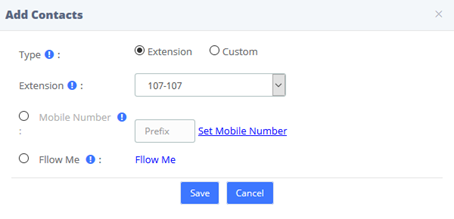
Figure 3-11-3 Add Contacts/Extension
Of course, you can also check Custom to enter other numbers. This number can be a mobile phone number, and the number can be called from an outside line.
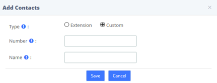
Figure 3-11-4 Add Contacts/Custom
Click  , you can select a contact group member to import into the current conference in batches.
Click  to save the participants of the current conference to a contact group, as shown in the figure below:
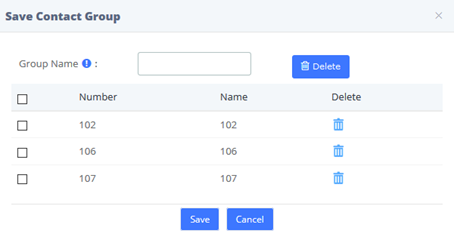
Figure 3-11-5 Save Contact Group
3.11.2 Conference Contacts
In this module, you can manage and add contact groups.
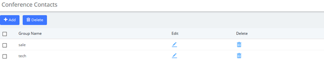
Figure 3-11-6 Conference Contact
Click  to add a contact group, as shown below:
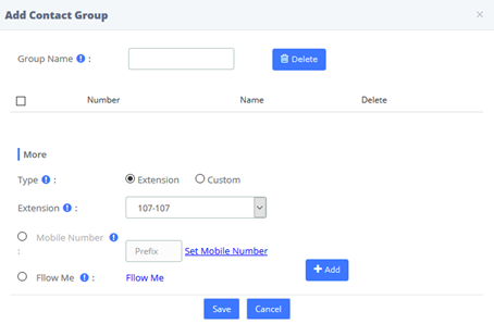
Figure 3-11-7 Add Contact Group
4 Fax
4.1 Virtual Fax
4.1.1 Virtual Fax List
The option Virtual Fax List of the Menu FAX in UC series lets us verify the list of all the virtual faxes, including the status of each one.
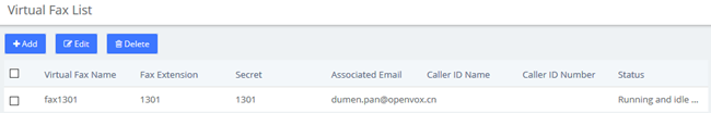
Figure 4-1-1 Virtual Fax List interface
Clicking on the name of the Virtual Fax will jump to a page displaying its information, in which you can Edit and Delete the Virtual Fax.
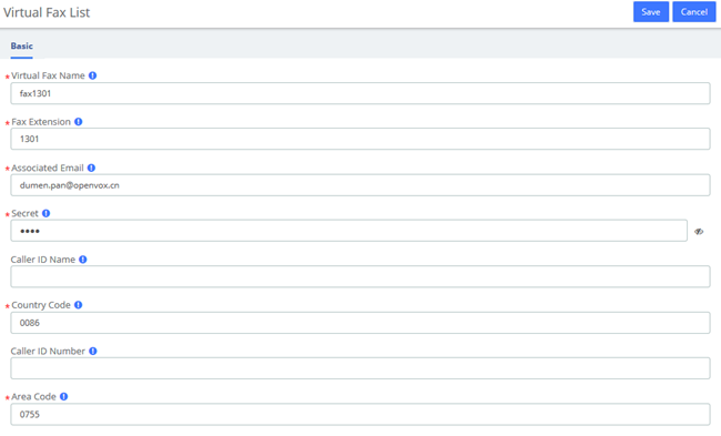
Figure 4-1-2 New Virtual Fax interface
Click Add you can create a new virtual fax. You should have previously created an IAX extension in PBX > Extensions > Add IAX2 Extension.

Figure 4-1-3 New Virtual Fax interface
To create a new virtual fax, enter the name, e-mail, extension, secret code, country code and area code for the virtual fax (these are the mandatory fields). After this information is added, click on the Save button to save the virtual fax.
4.1.2 Send Fax
The option Send Fax of the menu Fax in UC series allows sending faxes to one or more numbers. Here you can enter the text you want to send and click on Save button.
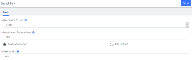
Figure 4-1-4 Send fax with text information
Also, you can send files in the format .pdf, .tiff and .txt
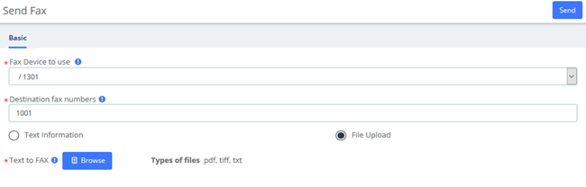
Figure 4-1-5 Send fax with File Upload
4.1.3 Fax Queue
The option Fax Queue from the Menu FAX in UC series shows the list of faxes that are awaiting its turn to be sent. All the jobs have an ID and a status so you can monitor the sending of the faxes. If you want to cancel a job, just select the job and click on Cancel Job button.
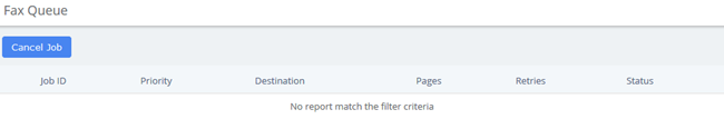
Figure 4-1-6 Fax Queue interface
4.2 Fax Master
The option "Fax Master" of the Menu "FAX" in UC series lets us input the email address of the administrator of the Fax, and this email will receive notifications of the messages received, errors and other activities of the Fax Server.

Figure 4-2-1 Fax Master Interface
4.3 Fax Clients
The option "Fax Clients" of the Menu "FAX" in UC series lets us input the IPs that have permission to send faxes through UC series.
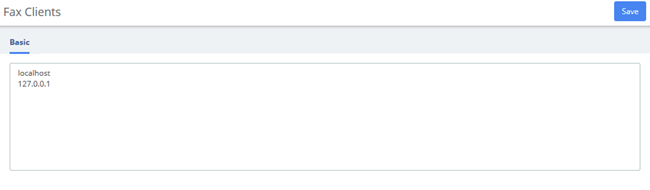
Figure 4-3-1 Fax Client interface
Proceed to input the IPs, one IP per line and click on the Save button.
It is recommended that you input the IP 127.0.0.1 and localhost in the configuration because some processes might need to use them.
4.4 Fax Viewer
The option "Fax Viewer" of the Menu "Fax" shows a list with all the faxes that have been sent and received in the virtual Faxes. You can download the faxes if you click on the name of the file.
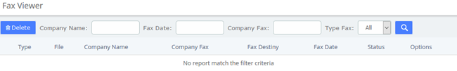
Figure 4-4-1 Fax Viewer interface
By the default all the files are shown, but you can filter according to company name, company fax, fax date or type fax.
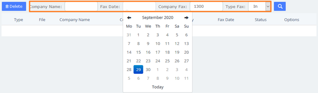
Figure 4-4-2 Fax Viewer show filter
5 Reports
5.1 CDR Report
The option CDR Reports of the Menu Reports in UC series lets us view a list with the details of the calls. You can download this list in different format files such as CSV, XLS and PDF.
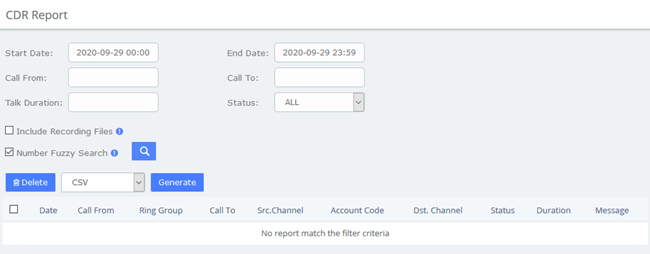
Figure 5-1-1 CDR Report interface
5.2 Channels Usage
The option Channels Usage of the menu Reports in UC series allows us view graphically the number of simultaneous calls for each channel.
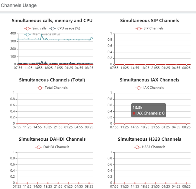
Figure 5-2-1 Channel usage interface
5.3 Graphic Report
The option Graphic Report of the Reports module allows visualizing graphically information about the number of calls, queues and trunks of the system both in quantity and percentage.
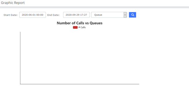
Figure 5-3-1 Graphic report interface
To see the information of a specific extension, select Extension (Number) and then click on the link fill in the extension number and click  .
.
It is possible to generate a graphic of Number of Calls in Queues. To do this just select Queue from the dropdown menu 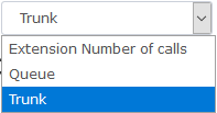 .
.
5.4 Summary
The option Summary of the menu Reports in UC series shows a report of each Extension registered in the server. You can see the number of incoming and outgoing calls, the duration of the calls, the caller id and the dialing number. Use the filter to find an extension or user.
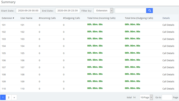
Figure 5-4-1 Summary interface
Click on Call Details to see more information of an extension.
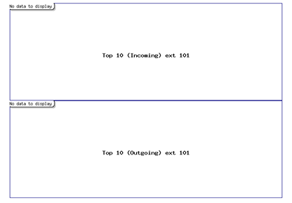
Figure 5-4-2 View Extension Call Details
5.5 Missed Calls
The option Missed Calls of the menu Reports in UC series shows a report of the missed calls of all extensions so you can know when an extension has been receiving calls. You can download this report by clicking on "Download" button. The available formats for this file are csv, xml and pdf
You can filter the results by:
- Start Date: Find missed calls from this date.
- End Date: Find missed calls until this date.
- Search: You can filter the results by these parameters:
- Source: Number that made the call.
- Destination: Number that received the call.
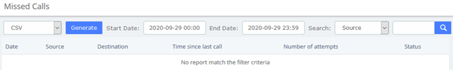
Figure 5-5-1 Missed calls interface
5.6 Downloads
In Downloads, users can find and download reports generated in previous modules by themselves, including CDRs, call recordings, event logs, missed calls, weak keys, audits, and more.
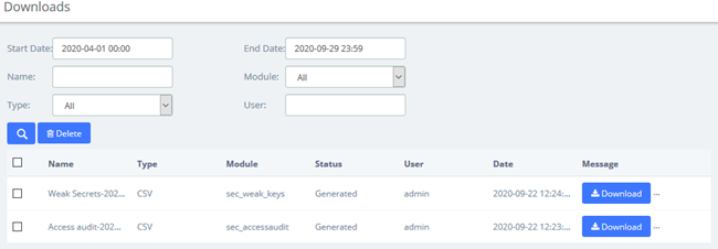
Figure 5-6-1 Downloads interface
6 Extras
6.1 Calling Cards
Calling Cards is a full-featured, flexible VoIP billing system and terminal platform that provides the fastest and lowest cost service for VoIP billing customers on the market today. This feature has been added to the new UC, and users who need it can enter the account password to log in.
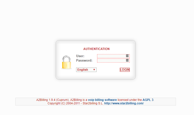
Figure 6-1-1 Calling Cards interface
6.2 Video Conference
Users can create video conferences in the IPPBX system, allowing multiple people to participate at the same time.
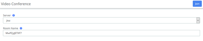
Figure 6-2-1 Video Conference interface
6.3 Hotel
6.3.1 Information
On the Extras > Hotel > Information page, you can see some information directly on this page.
The total rooms, how many available rooms (rooms free), or not (rooms busy), if you have some booking today, if your hotel is full or potentially full (caused by the booking).
If there's a booking today, just click on the  button to going to Booking list menu directly.

Figure 6-3-1 Hotel Information
6.3.2 Service
Room List
You can see the status of the rooms currently in your hotel. The guest name, the room name, if it's free or busy, cleaned or not. If the guest used the mini-bar or not. If the room is on DND (Do Not Disturb) status or not. And you can see if the room is included in a group or not.
If the phone device is a SIP phone, you can know if the phone is connected or not. In this case, you have a small yellow triangle beside the phone number.
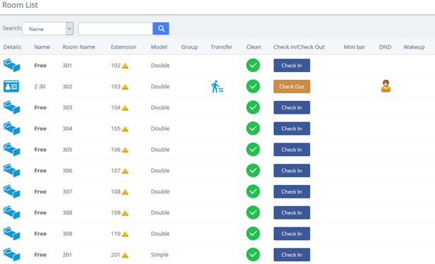
Figure 6-3-2 Room List
Check In
You can Check In for a new customer. You can see some fields to enter different values.
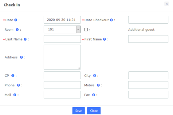
Figure 6-3-3 Check-In option
Date, it's the Check-in date (the current date by default). Date Checkout, is needed to have a reference in the case where another room will be booked. This information is not used for billing. Room, displays all available rooms into this list. Of course, you must enter a Last Name and First Name to making a check-in.
The other fields below are optional. However, one field is needed in the case where you want to sending the billing by mail. In this case, you must enter the Mail field. No billing will be sent by fax yet.
Once the guest is checked-in, you can click  and view the Guest’s info. Here you can see the customer's name, check-in time, check-out time, room price and other information.
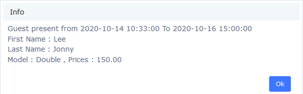
Figure 6-3-4 Guest Info
When the customer needs to change the room, select the  icon.
icon.
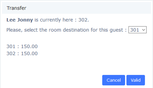
Figure 6-3-5 Transfer
If the customer has purchased a Mini-Bar item or made an outside call, the system will automatically transfer the customer's purchase and call costs to the new room.
And you also can check-in for a customer who have booked in Booking List:
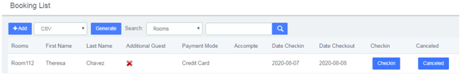
Figure 6-3-6 Check-in/Booking List
Or check-in for regular customers in Customers List:
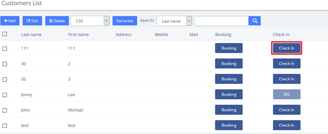
Figure 6-3-7 Check-in/Customers List
Check Out
You can do 2 types of checkout. A classic checkout by room, and a checkout by group.
When the customer needs to check out, select Check Out icon.

Figure 6-3-8 Check out by room
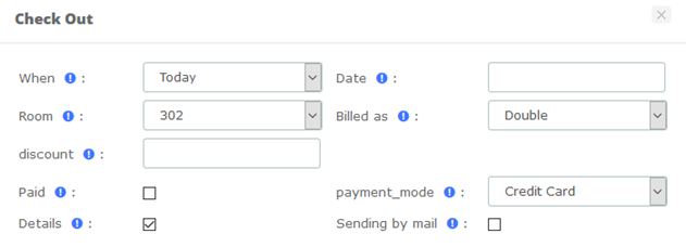
Figure 6-3-9 Check out by room options
If paid is checked, the billing is paid by the guest, else, this billing is tagged like not paid.
If you want to have all calls details for the room, check  .
.
If you want that guest receive its billing by mail, check  .
.
After checking out, you can check the billing report in Report > Billing Report.
Group List
Group List is used for unified management of customers who check-in in groups.

Figure 6-3-10 Group List
Here, you can see all group already existing, and you can add lots of checked rooms into a group in the same time. Just selecting several rooms maintaining, press the shift key and click on the rooms that you want.
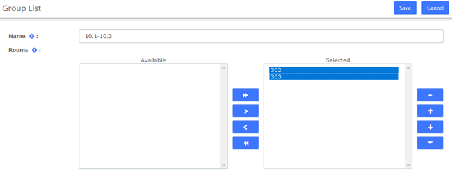
Figure 6-3-11 Group List options
Check Out
Checkout by group will take all room in group, and will make the checkout, room by room.
Check the group you want check out and click  . Checking out of 10.1-10.3 group means that both Room 302 and Room 303 will check out.
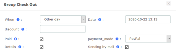
Figure 6-3-12 Check out by group option
When checking out, check Details to see the call bill.
Booking List
Here, you have all booking which currently entered into Hotel. You can do a view between 2 dates.
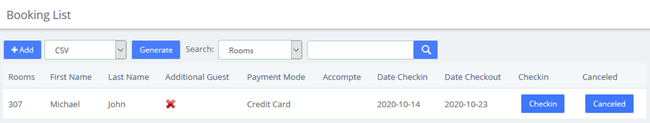
Figure 6-3-13 Booking List
Booking room for a new customer:
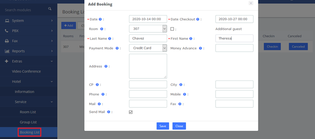
Figure 6-3-14 Add Booking
To make a checking on a booked room, click the Checkin box, and if you want to cancel a booking, check the Canceled box.

Figure 6-3-15 Check-in/Booking List
Booking room for a regular customer in the Customers List:
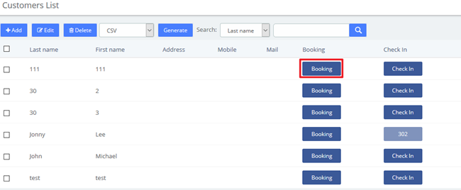
Figure 6-3-16 Check-in/Customers List
Customers List
All check-in and booking information will be entered into the customer list. This module can also customize customer information. You can book room or check-in for them.
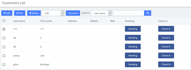
Figure 6-3-17 Customers List
Also, you can add a new customer.
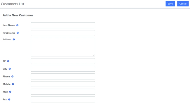
Figure 6-3-18 Add a New Customer
Wake Up
This module allows you to set up a wake-up call service for specific customers. The wake-up service will ring for 30 seconds every 30 seconds for the duration of the wake-up service.
In the following example, the wakeup service is set up for Room110's customers from 2020-08-04 11:46 to 2020-08-04 11:52.
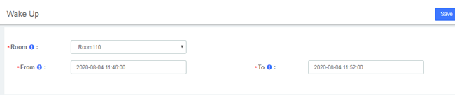
Figure 6-3-19 Wake Up options
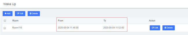
Figure 6-3-20 Wake Up Interface
The extension bound to Room110 will ring from 2020-08-04 11:46 to 2020-08-04 11:52
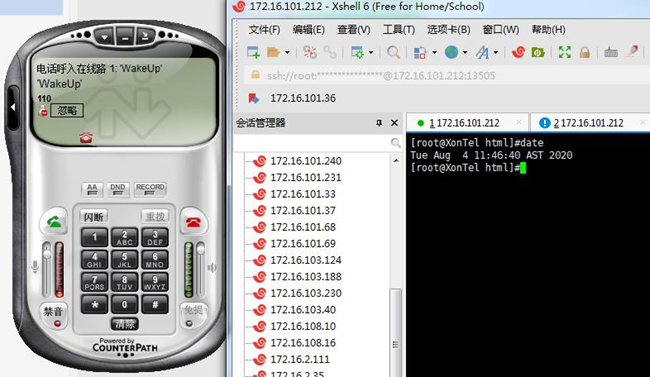
Figure 6-3-21 Wakeup Service
It can also be viewed or edited in the Room List module.

Figure 6-3-22 Room List/Wake Up
6.3.3 Configuration
Billing Settings
When the customer needs to use the extension to make an outside call, the service charge for the call is calculated based on the set call rate.
Billing Rates
If there is no matching rate list, the default rate will be used.
After initialized the rates, you can create a new billing rate or edit the existing rate.
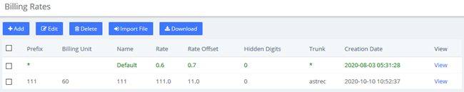
Figure 6-3-23 Billing Rates
Note: Only trunks allowed by Billing Trunk can be displayed in the tariff list.
Then create a new billing Rates:

Figure 6-3-24 Add/Edit Billing Rates
Billing Setup
You should initialize the billing rates before setting billing rules:
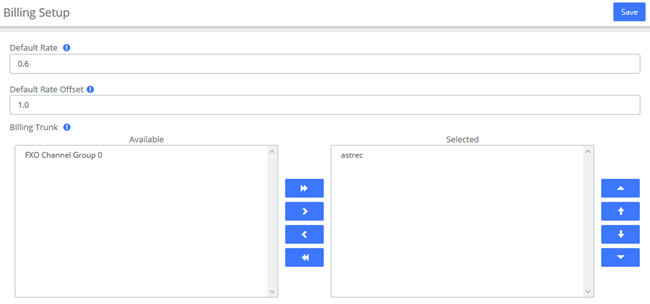
Figure 6-3-25 Billing Setup
Default Rate and Default Rate Offset set the rate of the Default billing rate. Billing Trunk sets the billing trunks allowed when creating new billing rates.
Room Setting
Room Setup
Once we have created the room type, we can generate the hotel room. Don't forget, try to prepare a good list of names for each room. (e.g.: room 100, room 101.etc). This name will be use by Hotel if no name is entered.
Click Add and create room.
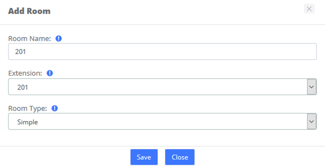
Figure 6-3-26 Add Room
Besides, you can click Add Bulk to batch create rooms.
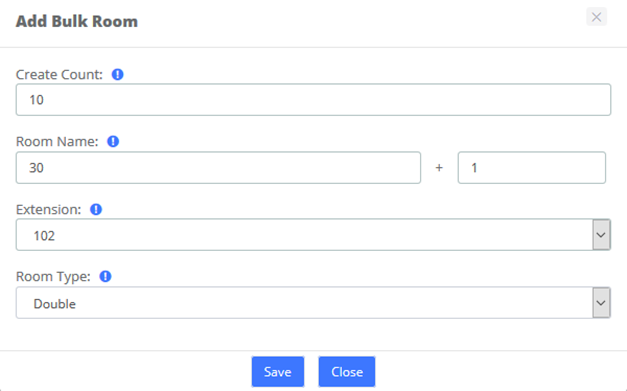
Figure 6-3-27 Batch initialization of rooms
Room Type
Room Type display all types already recorded into Hotel configuration.
Before to add any room, you must create some room type to putting them on each room. You can create hotel room types, such as common Standard Rooms, Double Rooms, Business Room, King Rooms, etc.
You could delete a room or more just selecting the checkbox at left of row.
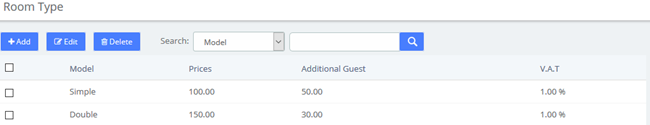
Figure 6-3-28 Room Types
Just putting a type with its price, enter a price to additional guest if you want, and select the V.A.T used by this room. (2 V.A.T. are enabled).
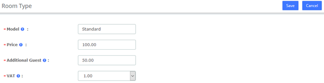
Figure 6-3-29 Room Types options
General
Before we begin, we should initialize the configuration of the hotel system, which includes customizing the company logo, company information, configuring emails, etc.
Here, you could select 2 operating mode (Hotel and Hospital). Now, only one operating mode is enabled.
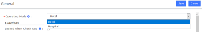
Figure 6-3-30 General/Operating Mode
You could select 3 basic functions in Hotel.
- Locked when checkout. When the room will be billed, this room will be locked. So impossible to calling a number.
- Calling between rooms: When checked, the room is able to call another room, but only if this room is included into the same group as the called room.
- Room must be clean: The room appear into the list of available room only if the room is cleaned. Else, the room will not appear into this list. However, this room could appear if you need to make a booking about this room.
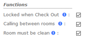
Figure 6-3-31 General/Functions
You can customize your company header, like the logo (png, or jpg file extension), the company address, and the professional mail of company.
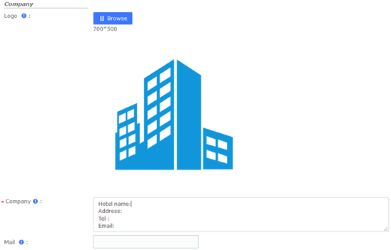
Figure 6-3-32 General/Company
Note: Mail is used to send Booking and Check-out reminders, and you need to configure the SMTP service in System->Email before using it.
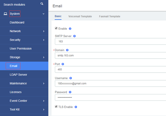
Figure 6-3-33 SMTP settings
You can customize or change the prefix of each hotel function. 3 Prefix exist right now.
- Mini-bar, is able to add some drinks on the room, and will used during the billing. When the chambermaid will clean the room, she could check the mini-bar and enter all drink used by the guest.
- Room Clean Prefix will used when the room will cleaned by the chambermaid.
- Reception is here to giving a phone number to the reception..
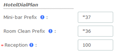
Figure 6-3-34 General/Hotel Dial Plan
Two tax values can be entered. The first value is used by the outbound calls during the billing.
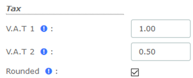
Figure 6-3-35 General/Tax

Figure 6-3-36 General/Discount
Mini Bar
Set up the items and VAT in the Mini-Bar. The waiter can dial to record the items purchased by the customer, dial the prefix (*37 by default) and press the number of the product used, ending with the * key. If you do not press the * key, the purchase will not be recorded. For example: if the customer has purchased three copies of Sprite, use the room’ extension to dial *37222*
This menu affecting a product on each key with its price. You can enter 10 different products on this module. 2 V.A.T can be selected.
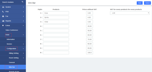
Figure 6-3-37 Mini Bar
If a customer has purchased an item, we can check it in the room list.
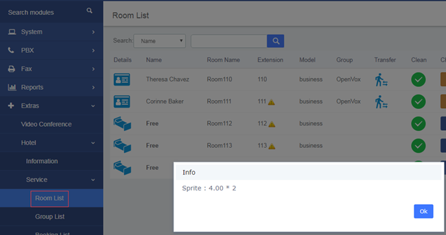
Figure 6-3-38 Room List/Mini Bar
Remote Action Control
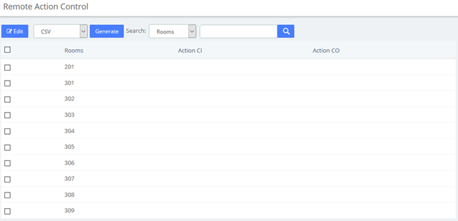
Figure 6-3-39 Remote Action Control
Booking Email Template
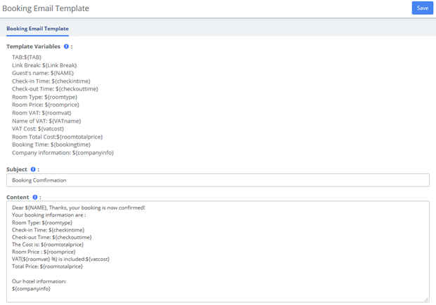
Figure 6-3-40 Booking Email Template
6.3.4 Report
Billing Report
You can check customer consumption in the Billing Report after checking out.
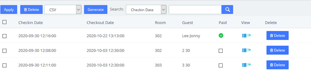
Figure 6-3-41 Billing Report list
Click you can view the billing report, and click can export this report.
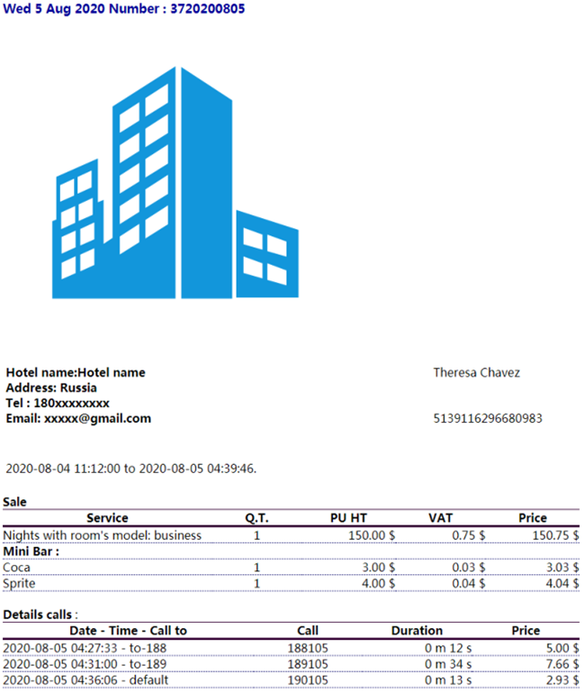
Figure 6-3-42 Billing Report
Call Billing Report
After the external call is over, the call record will be displayed in Hotel->Report->Call Billing Report.
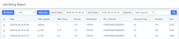
Figure 6-3-43 Call Billing Report list
Company Report
You can realize some company report, like how many checks in and checkout by day between two dates. Type of report include Check-in and Check-out info, Sum Rooms, mini-bar, calls, and billings.
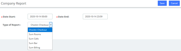
Figure 6-3-44 Company Report option
You can realize some company report, like how many check-in and checkout by day between two dates.
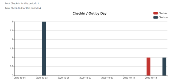
Figure 6-3-45 Company Report
7 Logs
7.1 Logs Settings
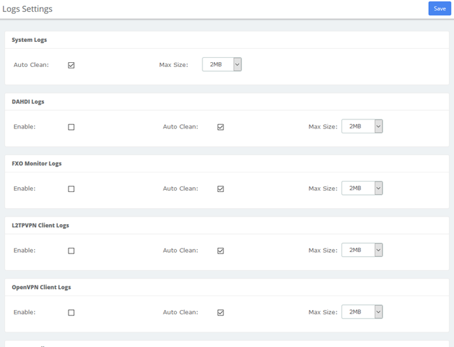
Figure 7-1-1 Logs Settings interface
7.2 System Logs
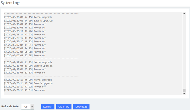
Figure 7-2-1 System Logs interface
7.3 Asterisk Logs
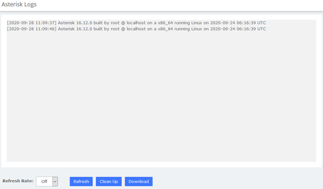
Figure 7-3-1 Asterisk logs interface
7.4 DAHDI Logs
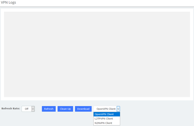
Figure 7-4-1 DAHDI logs interface
7.5 FXO Monitor Logs

Figure 7-5-1 FXO Monitor logs interface
7.6 VPN Logs
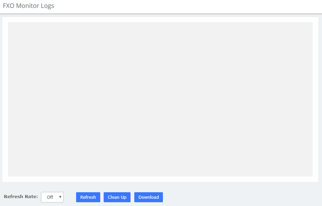
Figure 7-6-1 VPN logs interface
8 Me Bar
As mentioned in 2.4 User Permission, all SIP extensions will be given Me module permissions by default. Enter Me Bar interface requires login with extension account. On the login page of IPPBX, enter the Extension/User Password and click login. Note that the extension login uses the User Password, not the Registration Password. After the extension is logged in, as shown below
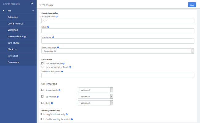
Figure 8-1 Me Bar interface
If the extension has set permissions in System>User Permission, the corresponding module will appear in the menu after the extension logs in. You can set the extension permissions flexibly and reduce the burden of the UC administrator. For details, see 2.4 User Permission.
8.1 Extension Number
Most of the parameters on this page can also be configured under the Administrator's management page (PBX>Extension>Edit).
You can set the basic information of the extension.
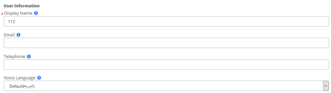
Figure 8-1-1 User Information
You can also set the Voicemail feature of the current extension:
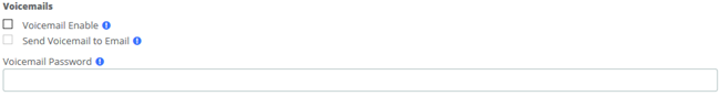
Figure 8-1-2 Voicemails
You can also set the Call Forwarding feature for the current phone, click the drop-down list to select Voicemails/Extension:

Figure 8-1-3 Call Forwarding
You can also set whether to enable the Mobility Extension feature (i.e. mobile phone number) for the current extension.
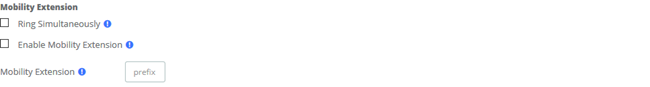
Figure 8-1-4 Mobility Extension
You can also set other functions of this extension.
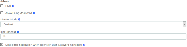
Figure 8-1-5 Others
8.2 Call and Recordings
You can view the call records and recordings related to the current extension
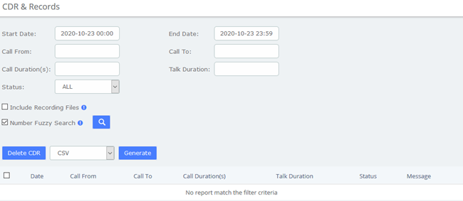
Figure 8-2-1 CDR & Records
When the extension is given permission to download CDRs, Generate button will appear, which can generate call detail records and you can download them on the Downloads page.
When the extension is given permission to delete the CDR, the Delete CDR button will appear. You can click the call log in the check box and click the button to delete it.
8.3 Voicemail
You can also check the voice messages of the changed extension
Figure 8-3-1 VoiceMail interface
8.4 Password Settings
You can reset the login password of the extension

Figure 8-4-1 Password setting
8.5 Black List
The Black List module is the same as the blacklist function under the admin account. You can add a phone number to a blacklist or remove a phone number from a blacklist. You can also choose to blacklist any blocked or unknown calls.
When a number is blacklisted, any calls with that number in the Caller ID field received by the system will be routed to the disconnected record.
Figure 8-5-1 Black List
8.6 White List
The White List module is the same as the whitelist function under the admin account.
Figure 8-6-1 White List
If enabled White Only, the incoming call will be limited. For example, if you add a 1000 in whitelist, and the type is Inbound, then only 1000 can dial in and reach this extension.
8.7 Downloads
The call records generated on the CDR page or the CDR & Records page of the Me Bar can be downloaded on the Downloads page.
If the extension is given permission to view and download, the download content of the specified extension can also be viewed on the page. For details, see 2.4 User Permission.
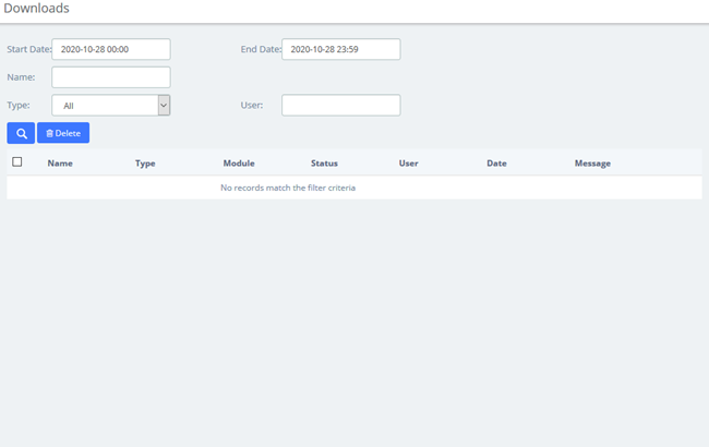
Figure 8-7-1 Downloads
9 Web Phone
If you have enabled Web Phone in PBX > Extensions > Extensions module under the admin account, you can enter the WebPhone module which supports all the functions of Me Bar, and use it to make calls directly. It should be noted that, since the underlying transmission of the VoIP uses the WSS protocol, this means that you cannot use WebPhone and other phones at the same time.
Recommend using Chrome browser.
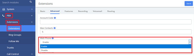
Figure 9-1 WebPhone page
9.1 Web Dialing
When entering the module for the first time, the extension is not registered and the dial cannot be used. You need to slide the  switch to turn it on. After it is turned on, the extension's transmission protocol will automatically become wss and be registered.
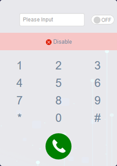
Figure 9-1-1 Dial
You can tap the dial pad on the page to dial, or input the number you want to dial, and then tap  to initiate the call. If the browser asks whether to enable the microphone, please allow it.
9.2 Contacts
Contacts can be understood as a phone book, and you can add frequently used contacts to this phone book to achieve speed dialing. The added contact is only visible to the current extension.
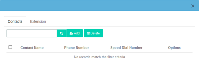
Figure 9-2-1 Contacts
Click Add to add a new contact, "Contact Name" and "Phone Number" options are required.
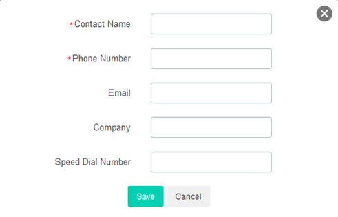
Figure 9-2-2 Add Contact
After checking the box, click Delete to delete contacts in batches. Of course, you can also click  to delete this contact.
Click  to directly dial the contact without entering the number.
Click  to edit this contact.
In this interface, you can also search for a contact, enter his/her name in the input box, or enter the phone number, and click the  button. If the contact is in the "Phonebook", the contact will be displayed, otherwise it will prompt "No records match the filter criteria".
The Extension tab will display all extensions in the IPPBX system, and will display the status of the extensions (Idle, Offline, Busy).
Click  to directly dial the currently online extension.
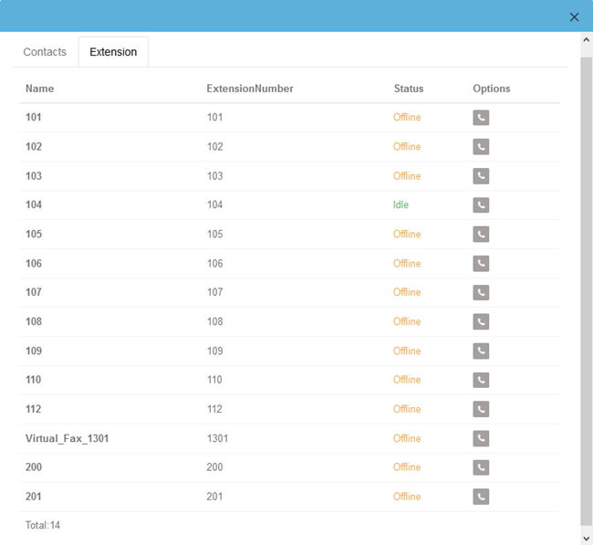
Figure 9-2-3 Extension
9.3 Settings
This setting page is basically the same as the Extension page in Me Bar.
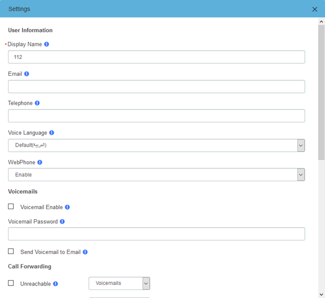
Figure 9-3-1 Settings
9.4 CDR
You can view the call details records and related recordings of the current extension
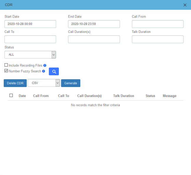
Figure 9-4-1 CDR
When the extension is given the permission to download call records, Generate button will appear, you can generate call records and download them in the download content.
When the extension is given the permission to delete call records, Delete CDR button will appear, you can select call records and delete.
9.5 VoiceMails
You can view the VoiceMail of the current extension.
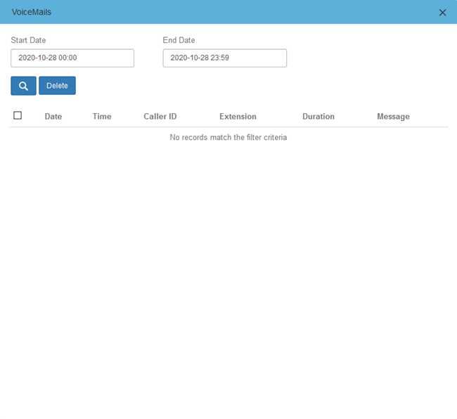
Figure 9-5-1 VoiceMails
9.6 Password Settings
You can modify the login password of the extension.
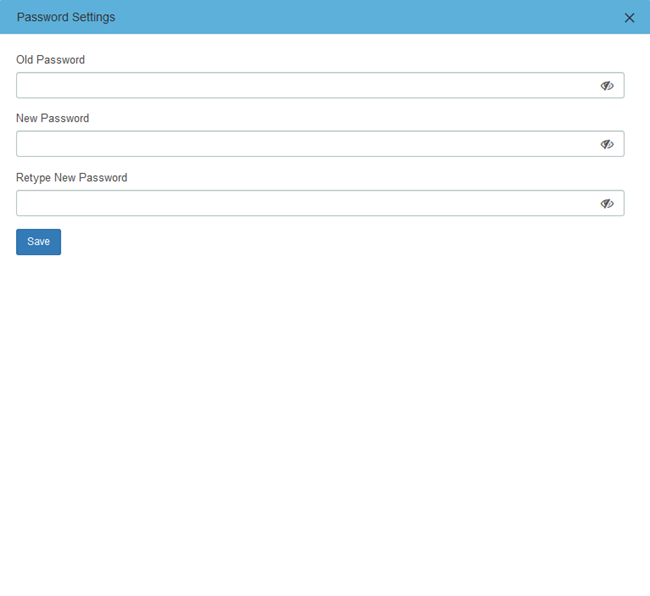
Figure 9-6-1 Password Settings
9.7 Functions Code
The function code page lists all the function codes that can be used on IPPBX. You can quickly configure/use the basic functions of system according to different function codes. For details, please refer to PBX>Settings>Function Codes.
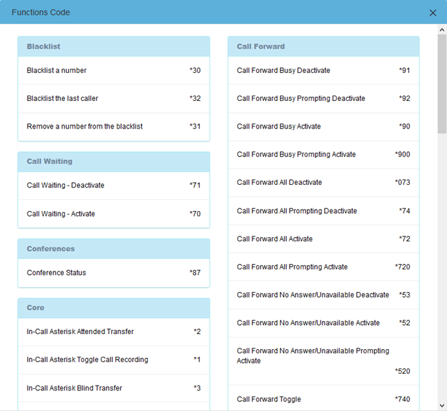
Figure 9-7-1 Functions Code
9.8 Downloads
The call records generated on the CDR page or the CDR & Records page of the Me Bar can be downloaded on the Downloads page.
If the extension is given permission to view and download, the download content of the specified extension can also be viewed on the page. For details, see 2.4 User Permission.
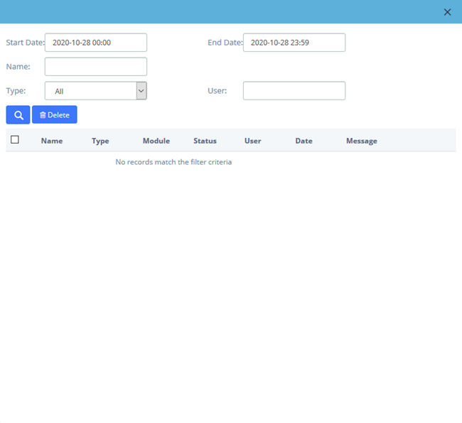
Figure 9-8-1 Downloads