...
It is developed with a wide selection of codecs and signaling protocol, including G.711A, G.711U, G.729, G.722, G.723 and GSM. It supports PRI/SS7/R2 protocol. OpenVox T1/E1 Gateway has good processing ability and stability and we provides 1/2/4 T1/E1 interface for your choice. The T1/E1 gateway will be 100% compatible with Asterisk, Elastix, trixbox, 3CX, FreeSWITCH SIP server and VOS VoIP operating platform.
Sample Application
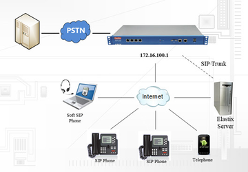
Figure 1-2-1Topological Graph
Product Appearance
The picture below is appearance of DGW-1004.
...
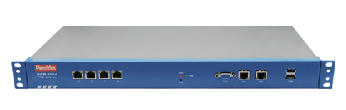
Figure 1-3-1 Product Appearance
...
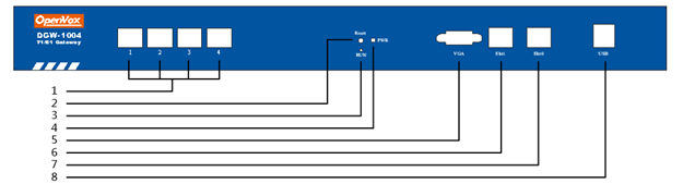
Figure 1-3-2 Front Panel
...
Table 1-3-1 Description of Front Panel
Interface | Function | Color | Work Status |
1 Port 1-Port4 | E1/T1 ports. The port numbers are different on different models, from 1 to 4. | ||
2 Reset | Reset button is used to restore the device. | ||
3 RUN | Register indicator | Green | Slow blinking(Green 2s and Flash 0.1s):Work normally |
Fast blinking(Green 0.5s and Flash 0.5s): Work abnormally | |||
Fast blinking(Green 0.5s and Flash 0.5s): Work abnormally | |||
No blinking: Dahdi Error | |||
4 PWR | Power Status indicator | Green | On: Power is on |
Off: Power is off | |||
5 VGA | VGA monitor connector | ||
6 Eth1 | Network interface | ||
7 Eth0 | Network interface | ||
8 USB | USB interface | ||
...

Figure 1-3-3 Backup Panel
The OpenVox DGW-100X series gateways provides one or two power supply, one power named DGW-100X ,the other is named DGW-100XR, ‘R’ stands for Reduntant.
Main Features
- Based on Asterisk
R- ®
- Editable Asterisk
R- ® configuration file
- Wide selection of codecs and signaling protocol
- Support
unlimited - 512 routing rules and flexible routing settings
- Stable performance, flexible dialing, friendly GUI
- Codecs support: G.711A, G.711U, G.729, G.723, G.722, GSM
- Support ports group management
- Support call status information
- Support T.38/Pass-through fax
- Support Auto Provision, SNMP V1/V2c/V3 and TR069
- Echo Cancellation
- Connect legacy PBX systems to low-cost VoIP services
- Connect legacy PBX systems to remote sites over private VoIP links
- Connect IP PBX systems to legacy TDM services
Physical Information
Table 1-5-1 Description of Physical Information
Weight |
...
2842 g | |
Size | 44cm* |
...
23cm*4. |
...
3cm | |
Temperature | - |
...
40~85°C (Storage) |
...
0~70°C (Operation) |
Operation humidity |
...
5%~95% non-condensing |
Max power |
...
20 W | |
LAN port | 1 |
WAN port | 1 |
...
...
Software
Default IP: 172.16.100.1
...
Password: admin
Notice: Log in
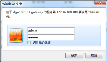
Figure 1-6-1 LOG IN Interface
2. System
Status
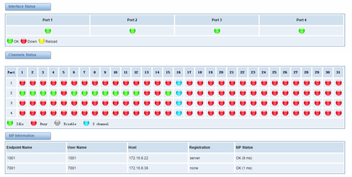
On the “Status” “System Status” page, you will find all Interface status, Channelschannels status, SIP, IAX2, Routing rules, and Network information and status.
...
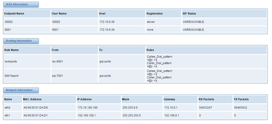
Figure 2-1-1 System Status
Table 2-1-1 Description of System Status
Options | Definition |
Interface Status | Show the status of port, include "OK" and ”Down”. "Down" means no trunk line connected; "OK" means the trunk line of port is available. |
ChannelsStatus | Show the Channels status of port, include "Idle". "Busy". "Disable" and “S channel”. "Idle" means it is available; "Busy" means the channel is busy; "Disable" means it is unavailable; “S channel” means signaling channel. |
Time
...
Call Status
The verbose of the system call status will be present on the “Call Status” page. You can select the specified T1/E1 port which you are care for.
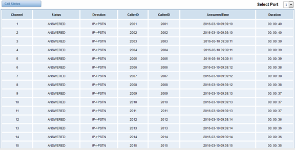
Figure 2-2-1 Verbose of call status
Time
Table 2-2-1Description of Time Settings
...
For example, you can configure like this:
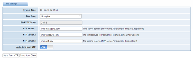
Figure 2-2-1 Time Settings
...
Your gateway doesn't have administration role. All you can do here is to reset what new username and password to manage your gateway. And it has all privileges to operate your gateway. You can modify “Web Login Settings” and “SSH Login Settings”. If you have changed these settings, you don’t need to log out, just rewriting your new user name and password will be OK. Also you can specify the web server port number. Usually the web login default mode is “http and https”. For safety, you can switch to “only https” mode.
Table 2-3-1Description of Login Settings
Options | Definition |
User Name | Your gateway |
...
does not have administration role. All you can do here is defining the user name and password to manage your gateway. And it has all privileges to operate your gateway .User Name: Allowed characters “-_+<>&0-9a-zA-Z”.Length:1-32 characters. | |
Password | Allowed characters "-_+. <>&0-9a-zA-Z". Length: 4-32 characters. |
Confirm Password | Please input the same password as 'Password' above. |
Login Mode | Specify the web login mode: http and https, only https. Default is http and https. |
Port | Specify the web server port number. Do not use port 443 which is reserved for HTTPS. |
...
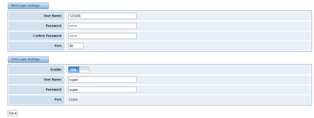
Figure 2-3-1 Login Settings
...
You can choose different languages for your system. If you want to change language, you can switch “Advanced” on, then “Download” your current language package. After that, you can modify the package with the language you need. Then upload your modified packages, “Choose File” and “Add”.
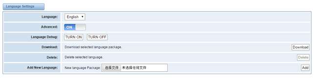
Figure 2-4-1 Language Settings
...
If switch it on, you can manage your gateway to reboot automatically as you like. There are four reboot types for you to choose, “By Day, By Week, By Month and By Running Time”.
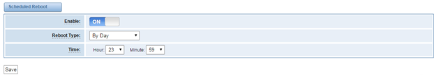
Figure 2-4-2 Reboot Types
...
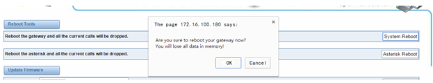
You can choose system reboot and Asterisk reboot separately.
...
Figure 2-5-1 Reboot Prompt
...
We offer 2 kinds of update types for you, you can choose System Update or System Online Update. System Online Update is an easier way to update your system, if you choose that, you will see some information below.
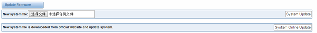
Figure 2-5-2Prompt Information
...
If you want to update your system and remain your previous configuration, you can first backup configuration, then you can upload configuration directly. That will be very convenient for you.
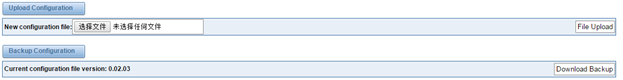
Figure 2-5-3 Upload and Backup
...
Sometimes there is something wrong with your gateway that you don’t know how to solve it, mostly you will select factory reset. Then you just need to press a button, your gateway will be reset to the factory status.

Figure 2-5-4 Factory Reset
...
On the “Information” page, there shows some basic information about the T1/E1 gateway. You can see software and hardware version, storage usage, memory usage and some help information.
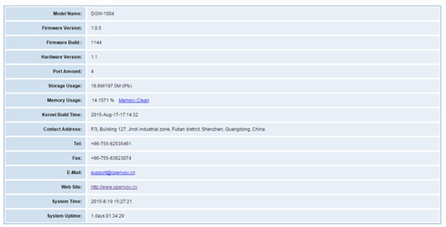
Figure 2-5-5 System Information
3. T1/E1
General
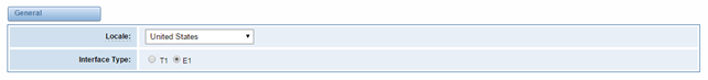
Figure 3-1-1 General Settings
...
Local | Your local. This will be used for the tone style. Used when in-call indications need to be generated such as ring back, busy, congestion, and other call-oriented inband tone signals. |
Interface Type | It shows you the current type of port. It has two type:E1 and T1 |
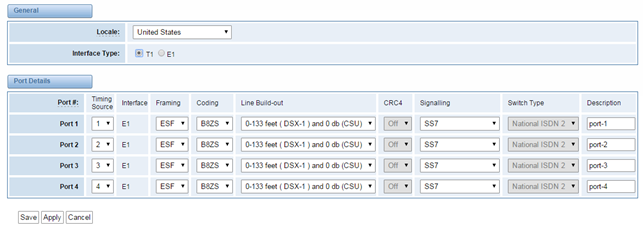
Table 3-1-2 Definition of advanced interface type
Options | Definition |
Echo Cancellation | Whether or not to enable echo cancellation |
RX Gain
| Gain for the RX (receive -into Asterisk)channel.Default:0.0 |
TX Gain
| Gain for the TX (transmit -out of Asterisk Asterisk)channel.Default:0.0 |
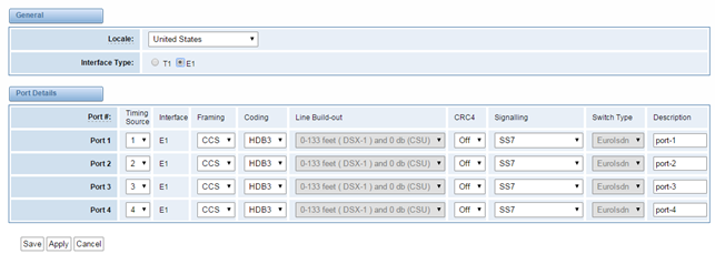
Figure 3-1-2 Port 2Port Details
...
Table 3-1-3 Definition of Port Details
...
ISDN-PRI
Advanced: Interface Type
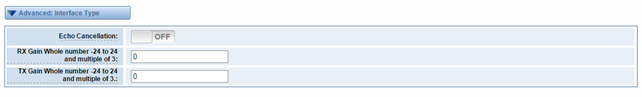
Figure 3-2-1 Advanced: Interface Type
...
Options | Definition |
Echo Cancellation | Whether or not to enable echo cancellation on this line |
RX Gain Whole number -24 to 24 and multiple of 3 | Gain for the rx (receive -into Asterisk)channel.Default:0.0 |
TX Gain Whole number -24 to 24 and multiple of 3 | Gain for the tx(transmit -out of Asterisk Asterisk)channel.Default:0.0 |
ISDN: Signaling
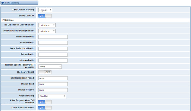
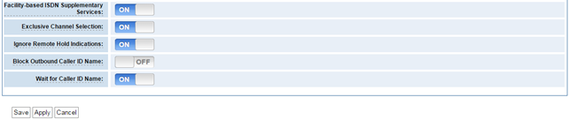
Figure 3-2-2 ISDN: Signaling
...
Options | Definition |
Q.SIG Channel Mapping | Sets logical or physical channel mapping. In logical channel mapping, channels are mapped to 1-30.In physical channel mapping, channels are mapped to 1-15,17-31,skipping the number used for the data channel, Default is physical. |
Enable Caller ID | Whether or not to use caller ID |
PRI Dial Plan for Dialed Number | PRI Dialplan: The ISDN-levei Type of Number (TON) or numbering plan, used for the dialed number. Leaving this as ‘unknown’ (the default) works for most cases. In some very unusual circumstances, you may need to set this to; ’dynamic’ or ‘redundant’ |
PRI Dial Plan for Dialing Number | PRI Local Dialplan: Only RARELY used for PRI(sets the calling number’s numbering plan).In North America, the typical use is sending the 10 digit; caller ID number and setting the prilocaldialplan to ‘national’ (the default).Only VERY rarely will you need to change this. |
Network Specific Facility (NSF) Messages | Some switches (AT&T especially) require network specific facility IE. Supported values are currently ‘none’,’sdn’,’ megacom’,’ tollfreemgacom’, ’ account’ |
Idle Bearer Reset | Whether or not to reset unused B channels |
Idle Bearer Reset Period | Sets the time in seconds between restart of unused B channels; defaults to ‘never’ |
Display Send | Send/receive ISDN display IE options, the display options are a comma separated list of the following options: Block: Do not pass display text data. Name_ initial: Use display text in SETUP/CONNECT messages as the party name. Name_ update: Use display text in other messages (NOTIFY/FACILITY)for COLP name update. Name: Combined name_ initial and name_ update options. Text: Pas any unused display text data as an arbitrary display message during a call. Sent text goes out in default to ‘name’ |
Display Receive | Send/receive ISDN display IE options. The display options are a comma separated list of the following options: Block: Do not pass display text data. Name_ initial: Use display text in SETUP/CONNECT messages as the party name. Name_ update: Use display text in other messages (NOTIFY/FACILITY) for COLP name update. Name: Combined name_ initial and name_ update options. Text: Pas any unused display text data as an arbitrary display message during a call. Sent text goes out in default to ‘name’ |
Overlap Dialing | Enable overlap dialing mode--sending overlap digits. |
Allow Progress When Call Released | Allow inband audio (progress) when a call is DISCONNECT Ted by the end of a PRI |
Out-of-Band Indications | PRI Out of band indications. Enable this to report Busy and congestion on a PRI using out_ of_ band notification. Inband indication, as used by the gateway doesn’t seem to work with all telcos. |
Facility-based ISDN Supplementary Services | To enable transmission of facility-based ISDN supplementary services (such as caller name form CPE over facility), enable this option. Cannot be changed on a reload. |
Exclusive Channel Selection | If you need to override the existing channels selection routine and force all PRI channels to be marked as exclusively selected, set this to yes. priexclusive cannot be changed on a reload. |
Ignore Remote Hold Indications | If you wish to ignore remote hold indications (and use MOH that is supplied over the B channel) enable this option. |
Block Outbound Caller ID Name | Enable if you need to hide just the name and the number for legacy PBX use. Only applies to PRI channels. |
Wait for Caller ID Name | Support caller ID on call waiting |
SS7
Link Set Settings
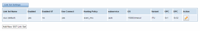
Figure 3-3-1 Link Set Settings
You can click button as shown below, when there are several link set, only one can be set to the default.
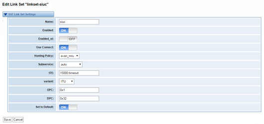
Figure 3-3-2 SS7 Link Set Settings
...
options | Definition |
Name | The linkset’s name |
Enabled | The linkset is enable or disable |
Enabled_ st | The end_of_pulsing (ST) is not used to determine when incoming address is complete |
Use Connect | Reply incoming call with CON rather than ACM and ANM |
Hunting Policy | The CIC hunting policy (even_mu, odd_lru, seq_lth, seq_htl) is even CIC numbers, most recently used |
Subservice | The subservice field: national (8), international l(0), auto or decimal/hex value; The auto means that the subservice is obtained from first received SLTM. |
t35 | The value and action for t35. Value is in msec, action is either st or timeout; if you use overlapped dialing dial plan, you might choose:t35=>4000,st |
variant | Running under SS7 standard |
OPC | The point code for this SS7 signaling point |
DPC | The destination point (peer) code |
Set to Default | Set the linkset as the default linke set |
Link Settings
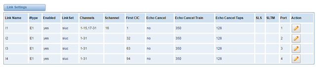
Figure 3-3-3 Link Settings
You can click  button as shown below.
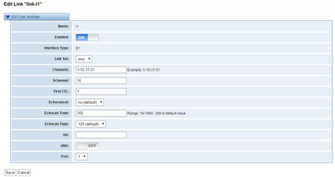
Figure 3-3-4 SS7 Link Settings
...
SS7 Config. File Backup and Restore
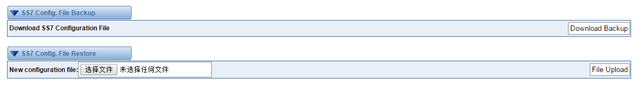
Figure 3-3-5 Config. File Backup and Restore
...
MFC/R2
Advanced: Interface Type
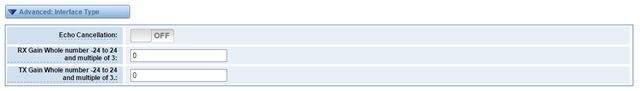
Figure 3-4-1 Advanced: Interface Type
...
options | Definition |
Echo Cancellation | Whether or not enable echo cancellation on this line |
RX Gain Whole number -24 to 24 and multiple of 3 | Gain for the rx (receive_ into Asterisk) channel. Default:0.0 |
TX Gain Whole number -24 to 24 and multiple of 3 | Gain for the tx (receive_ into Asterisk) channel. Default:0.0 |
MFC/R2: Signaling

Figure 3-4-2 MFC/R2: Signaling
...
This page shows everything about your SIP, you can see status of each SIP.
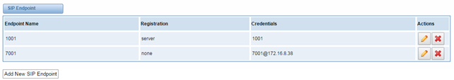
Figure 4-1-1 SIP Status
Main Endpoint Settings
You can click button to add a new SIP endpoint, and if you want to modify existed endpoints, you can click
 button.
There are 3 kinds of registration types for choose. You can choose Anonymous, Endpoint registers with this gateway or This gateway registers with the endpoint.
...
If you set up a SIP endpoint by registration “None” to a server, then you can’t register other SIP endpoints to this server. (If you add other SIP endpoints, this will cause Out-band Routes and Trunks confused.)
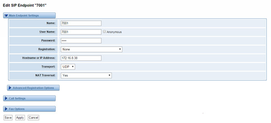
Figure 4-1-2 None Registration
For convenience, we have designed a method that you can register your SIP endpoint to your gateway, thus your gateway just work as a server.
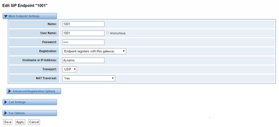
Figure 4-1-3 Endpoint Register with Gateway
Also you can choose registration by “This gateway registers with the endpoint”, it’s the same with “None”, except name and password.
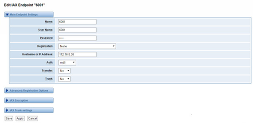
Figure 4-1-4 This Gateway Register with the Endpoint
...
Options | Definition |
Mode | Working mode T.38 and T.30 |
Enabled | Enabled |
Error Correction | Error Correction |
Max Datagram | In some cases,T.38 endpoints will provide a T38FaxMxDatagram value (during T.38 setup) that is based on an incorrect interpretation of the T.38 recommendation, and result in failures because Asterisk does not believe it can send T.38 packets of a reasonable size to that endpoint (Cisco media gateway are one example of this situation).In these cases, during a T.38 call you will see warring messages on The console/in the logs from the Asterisk UDPTL stack complaining about lack of buffer space to send T.38FaxMaxDatagram value specified by the other end[point, and use a configured value instead. |
Fax Detect | FAX detection will cause the SIP channel to jump to the ‘faX’ extension (if exists) based one or more events being detected. The events that can be detected are an incoming CNG tone or an incoming T.38 re-INVITE request. |
Fax Activity | activate T38 fax gateway with ‘timeout’ seconds |
Fax Timeout | activate T38 fax gateway with ‘timeout’ seconds |
IAX2 Endpoint
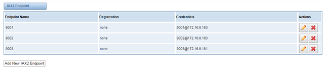
Figure 4-1-5 IAX2 Endpoint
You can click button as shown below
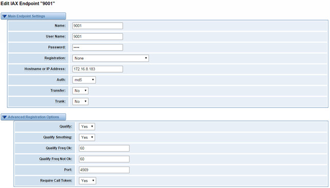
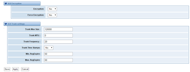
Figure 4-1-6 Edit IAX Endpoint "9001"
...
Select codecs from the list below.
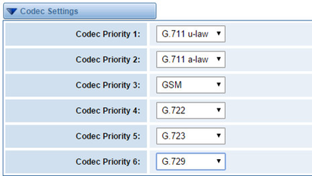
Figure 4-2-1 Codec Settings
...
Options | Definition |
Udptl Start | DPTL start configure addresses |
Udptl End | DPTL end configure addresses |
Udptl Checksums | Whether to enable or disable UDP checksums on UDPTL traffic |
Udptl Fec Entries | The number of error correction entries in a UDPTL packet |
Udptl Fec Span | The span over which parity is calculated for FEC in a UDPTL packet |
Use Even Ports | Some VoIP providers will only accept an offer with an even-numbered UDPTL port. Set this option so that Asterisk will only attempt to use even-numbered ports when negotiating T.38. Default is no. |
Maximum Transmission Rate | Maximum Transmission Rate |
Minimum Transmission Rate | Minimum Transmission Rate |
Send Progress/Status events to manager session | Manager events with ‘call’ class permissions will receive events indicating the steps to initiate a fax session. Fax completion events are always sent to manager sessions with ‘call’ class permissions, regardless of the value of this option. |
Modem Capabilities | Set this value to modify the default modem options. Defasult:v17,v27,v29 |
ECM | Enable/disable T.30 ECM(error correction mode) by default |
5. Routing
...
The gateway embraces the flexible and friendly routing settings for user. It supports up to 512 routing rules and about 100 pairs of calleeID/callerID manipulations can be set in a rule. It support DID function (The usage of DID function: How to use DID function with OpenVox T1/E1 Gateway). The gateway support trunk group and trunk priority management.
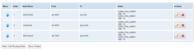
Figure 5-1-1 Routing Rules
You are allowed to set up new routing rule by , and after setting routing rules, move rules’ order by pulling up and down, click
  button to edit the routing and
 to delete it. Finally click the
  button to save what you set.
 shows current routing rules. Otherwise you can set up unlimited routing rules.
...
There is an example for Routing rules number conversion, it transform calling, called number at the same time. Suppose you want eleven numbers start at 159 to call the eleven numbers of start at 136. Calling transform delete the three numbers from left, then writing number 086 as prefix, delete the last four numbers, and then add number 0755 at the end, it will show caller name is openvox China Telecom. Called transform adds 086 as prefix , and Change the last two number to 88.
...
processing rules | prepend | prefix | Match pattern | SdfR | StA | RdfR | Caller Name |
Calling Transformation | 086 | 159 | ×××××××× | 4 | 0755 | OpenVox | China Telecom |
Called transformation | 086 | 136 | ×××××××× | 2 | 88 |
| N/A |
...
You can click button to set up your routings.
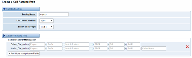
Figure 5-1-3 Example of Set Up Routing Rule
...
You can create various time routes and use these time conditions to limit some specific calls.
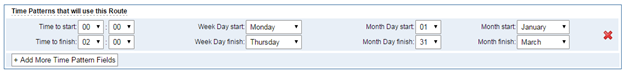
Figure 5-1-4Time Patterns that will use this Route
If you configure like this, then from January to March, from the first day to the last day of these months, from Monday to Thursday, from 00:00 to 02:00, during this time (meet all above time conditions), all calls will follow this route. And the time will synchronize with your Sever time.
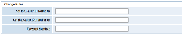
Figure 5-1-5Change Rules
You can set your caller ID name and caller number as you like before sending the call to the endpoint. You can also configure forward number when you have a transfer call.
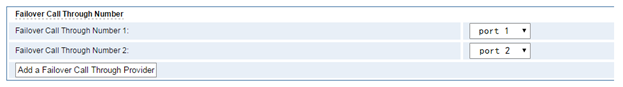
Figure 5-1-6 Failover Call Through Number
...
Sometimes you want to make a call through one port, but you don’t know if it is available, so you have to check which port is free. That would be troublesome. But with our product, you don’t need to worry about it. You can combine many Ports or SIP to groups. Then if you want to make a call, it will find available port automatically.
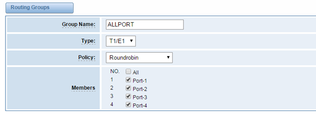
Figure 5-2-1 Establish Group
...
There are two types of WAN port IP, Static and DHCP. Static is the default type, and it is 172.16.100.1. The LAN port is a fixed IP and it is 192.168.100.1.
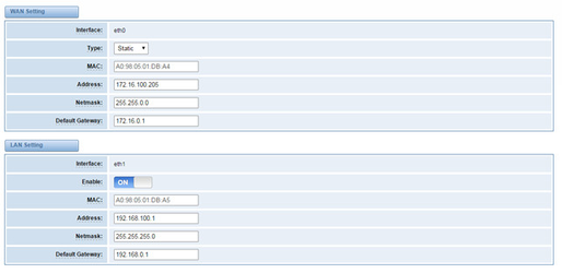
Figure 6-1-1 WAN/LAN Settings Interface
...
Basically this info is from your local network service provider, and you can fill in four DNS servers.
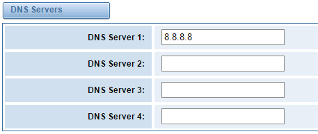
Figure 6-1-2 DNS Interface
...
You can enable or disable DDNS (dynamic domain name server).
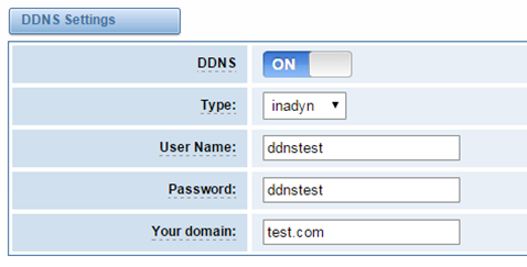
Figure 6-2-1 DDNS Interface
...
It is used to check network connectivity. Support Ping command on web GUI.
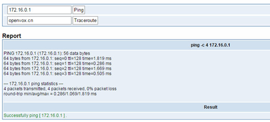
Figure 6-3-1 Network Connectivity Checking
...
When you make “Enable” switch to “ON”, this page is available.
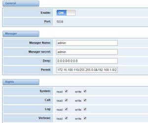
Figure 7-1-1 API Interface
...
Once you set like the above figure, the host 172.16.100.110/255.255.0.0 is allowed to access the gateway API. Please refer to the following figure to access the gateway API by putty. 172.16.100.110 is the gateway’s IP, and 5038 is its API port.
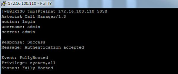
Figure 7-1-2 Putty Access
...
In this page, you are allowed to run Asterisk commands.
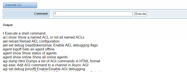
Figure 7-2-1 Asterisk Command Interface
...
On this page, you are allowed to edit and create configuration files.
Click the file to edit.
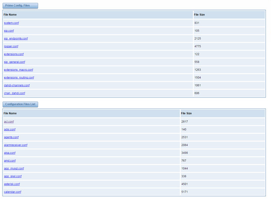
Figure 7-3-1 Configuration Files List
Click “New Configuration File” to create a new configuration file. After editing or creating, please reload Asterisk.
8. Logs
...
Auto Provisioning
Auto provisioning or auto-configuration is an easy, flexible and time-saving way to upgrade firmware and configurations for E1 gateways in mass deployment. With auto provisioning, all user information can be entered via the central ACS (Auto Configuration Server). ACS can be DHCP server or TFTP, HTTP and FTP server. It will not take effects immediately but in the next time system is power on. It could be postponed the execution of restart system also.
Note that system will not be upgrade the firmware and update configurations if the connection between ACS and gateway is disconnect.
Preparation
The following should be prepared before anto provisioning being applied.
l Enable the auto provisioning in gateway
l The ACS has been prepared
l The network between gateway and ACS is connected
Configuring gateway
Usually, the feature is disabled before being on sale. To activate the auto provisioning function, please follow the procedures as below.
Step 1 On the ADVANCED-> Auto Provision interface
Step 2 Enable the ‘Enabled’ option and select ACS. DHCP option 66 can be enabled if ACS has been work as DHCP server, otherwise please select protocol of provisioning and fill the value of ‘Auto Config Server URL’. Username and password may need to be filled in FTP/HTTP for the purpose of system safety. Do not forget to select Firmware upgrade, upgrade mode and fill the value of timeout, and click ‘Save’.
Step 3 Set interval of checking in LOGS->System notice then enable it, and click ‘Save’.
Table 7-4-1 Definition of Auto Provision
Options | Definition |
Enabled | Whether to enable or disable Auto Provision |
DHCP Option 66 | Get ACS server address from Option 66 via DHCP |
Protocol | Set protocol of connection |
Auto Config Server URL | The config server domain or IP address |
User Name | The account of downloading from ACS |
Password | The password of downloading from ACS |
Timeout | The max limit time for downloading firmware |
Firmware Upgrade | Enable/disable the mode of downloading firmware |
Upgrade Mode | Select upgrade time. Power: start upgrade configuration when Power on. Power + Period: Set the frequency of checking the latest configuration when gateway running |
Table 7-4-2 Definition of system notice
Options | Definition |
Enable | Whether to enable or disable system notice |
Check Interval | When Upgrade Mode is set, this parameter specifies the interval of Checking. |
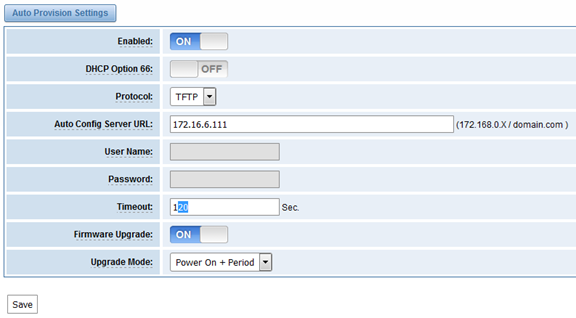
Figure 7-4-1 Auto Provision interface
Configuring ACS
The Auto Configuration Server can be the one of TFTP, FTP and HTTP server. The ACS is used to store the firmware release and configurations files of the devices under management.
List the primary files in ACS download directory as table 7-4-3:
Table 7-4-3 Definition of ACS files
Options | Definition |
DGW100x-current.bin | The firmware image |
common.conf | The wildcard configuration file for the whole gateway |
defconfig.tar.gz | The default(factory) configuration file |
EPC-{mac}.conf | The private configuration file for the specified gateway. Naming rules: “EPC-“ + “mac” +”.conf”. The naming prefix of “EPC-” stands for the private configuration file, “mac” is the physical address of network interface card but removed semicolon and “.conf” is the suffix. For example, the EPC-a0980501dbca.conf, ‘a0980501dbca’ is the MAC address (A0:98:05:01:DB:CA). |
The format of common.conf , EPC-{mac}.conf and defconfig.tar.gz:
(1). Common.conf
[firmware]
FW_NAME=DGW100x-current.bin //Firmware image name
FW_MD5=b3603f3c3b5e7eb6326498640f151c79 //The md5 of firmware image
FW_VERSION=1.1.2 //Firmware version
[configs]
CONFIG_NAME=defconfig.tar.gz // default configuration file(compressed)
CONFIG_MD5KEY=2cd2dfbe52482405350816e3698cb530 // the md5 of default configuration file
(2).EPC-{mac}.conf
[dns]
DNS_SERVER1=8.8.8.8
DNS_SERVER2=8.8.4.4
DNS_SERVER3=
DNS_SERVER4=
[ntp]
NTP_SERVER1= 0.cn.pool.ntp.org
NTP_SERVER2= time.nist.gov
NTP_SERVER3= time.windows.com
[eth0]
ENABLE=yes
TYPE=static
DHCP=no
IPADDRESS=172.16.100.223
NETMASK=255.255.0.0
GATEWAY=172.16.0.1
[eth1]
ENABLE=yes
TYPE=static
DHCP=no
IPADDRESS=192.168.100.223
NETMASK=255.255.0.0
GATEWAY=192.168.0.1
[web_login]
username=admin
password=admin
(3). Defconfig.tar.gz
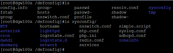
Figure 7-4-2 the overview of defconfig.tar.gz
Provisioning example
After auto provisioning is enabled, the gateway will visit the Auto Configuration Server and download the updated files periodically based on the timer Check Interval (LOGS->System notice). By default, the timer is set as every hour. System will receive a message from ACS, like figure 7-4-3, and the message will be display in the system notice (LOGS->System Notice).
Auto provisioning will not take effects immediately but in the next time system is power on. It could be postponed the execution of restart system also.
Now, an example of using Auto Provisioning will be given in the following.
- Activate the auto provision (TFTP) in ADVANCED-> Auto Provision like figure 7-4-4.
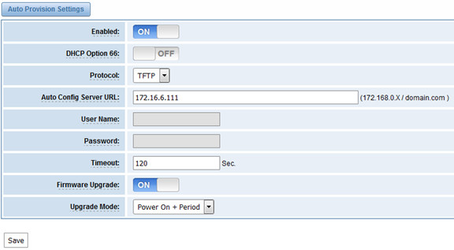
Figure 7-4-4 Auto provision settings
- Enable the check interval in LOGS->Log settings->System Notice like figure 7-4-5.
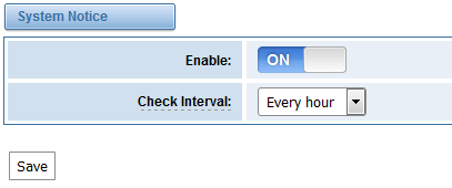
Figure 7-4-5 Check interval setting
- Configuring the ACS(Generate the md5 of firmware and defconfig.tar.gz)
l Copy the firmware, defconfig.tar.gz, common.conf and EPC-{mac}.conf to the working directory of TFTP server.
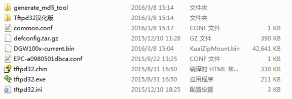
Figure 7-4-6 The working directory of TFTP server
Notice:
The demo of E1 gateway mac address is A0:98:05:01:DB:CA (eth0), therefore the private configuration file is EPC-a0980501dbca.conf.
l Generate the md5 of firmware and defconfig.tar.gz. Then fill in common.conf and EPC-{mac}.config.
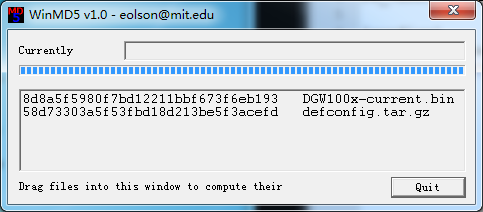
Figure 7-4-7 Generate the md5 of firmware and configuration
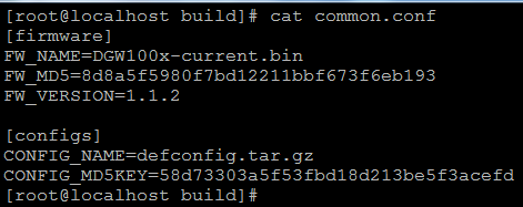
Figure 7-4-8 Common.conf
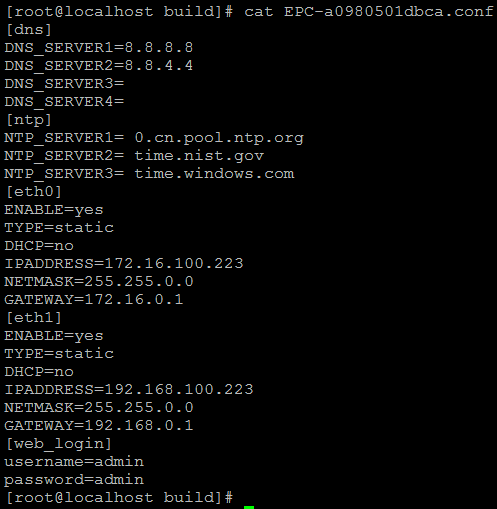
Figure 7-4-7 EPC- a0980501dbca.conf
l Start TFTP service. Tftpd32.exe is a useful TFTP tools in windows7, then make sure TFTP server is select.
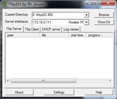
Figure 7-4-8 Demo TFTP server
- The system will receive an auto provision message in web GUI.
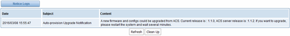
Figure 7-4-9 System notice logs
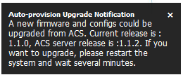
Figure 7-4-10 Auto provision upgrade notification
2.Restart the system. It will take about 3 minutes almost to download, upgrade Firmware and update configurations.
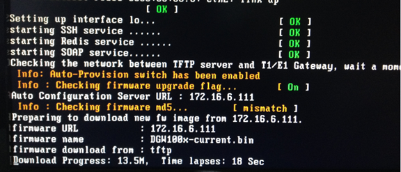
Figure 7-4-11Downloading the firmware and configs
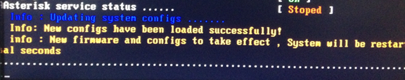
Figure 7-4-12Applying the firmware and configs
SNMP
Simple Network Management Protocol (SNMP) is an application–layer protocol, which is used to manage and monitor network elements and exchange management information between network devices. By default SNMP uses port 161 for communication.
Since the inception SNMP, it embraces three versions: v1, v2c and v3. V1 and v2c are the most implemented version of SNMP; v3 is target at the high security when compare to its older versions. The gateway support private SNMP MIBs (private enterprise number) to access.
Parameters in SNMP setting
Table 7-5-1Definition of SNMP setting
Options | Definition |
SNMP Enable | Whether to enable SNMP |
System Contact | System contact information(optional) |
System Location | The locale of system contact(optional) |
Private Enterprise Number | The number is used for defining private SNMP MIBs which is assigned by Internet Assigned Numbers Authority (IANA). For more information, please access: |
SNMP Version | Select version of SNMP |
Community Configuration | Define a community name to security name |
Group Configuration | Define the security name to a group |
View Configuration | Set a view to let the group have rights to do |
Access Configuration | Grant the group can access to the view(read/write/notify) |
User Configuration | Only exist in v3. Add a v3 account to SNMP. Notice that the length of auth password and privacy password are more than 8. |
Activating SNMP
Usually, the feature is disabled by default. To activate the SNMP feature, please follow the Figure 7-5-1.
The Interface is in the ADVANCED->SNMP. System contact, location and private enterprise number are optional. Figure 7-5-1 is the SNMP setting interface.
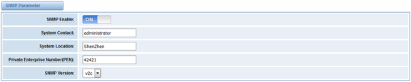
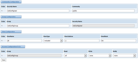
Figure 7-5-1 Activating the SNMP
Note: Do not forget to click ‘Save’ to take effect. After configuration, The SNMP feature is activated immediately.
Verify SNMP
A powerful, indispensable and easy-to-use MIB browser is convenient for engineer/manager to manage SNMP enabled network devices and applications. In this session, Manage Engine MIB browser is selected. It allows user to issue SNMP requests to retrieve agent's data, or make changes to the agent. It is free tool for Windows, Mac and Linux.
(1). Get SNMP parameters via SNMP MIB browser. It’s supposed that Manage Engine MIB browser is installed perfectly. Figure 7-5-2 is the main interface of Manage Engine MIB browser.
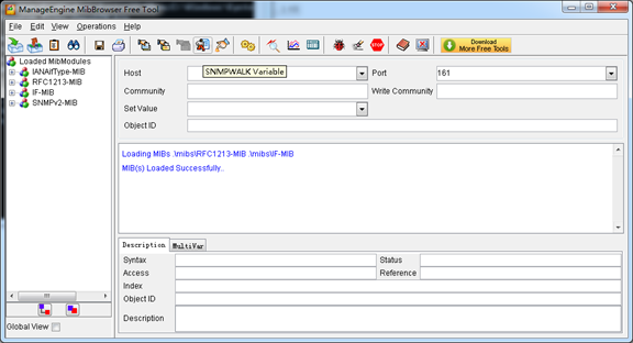
Figure 7-5-2 Manage Engine MIB browser
And the field of Host, Port and Community are filled with 172.16.100.223, 161 and public respectively. Object ID is the node of SNMP MIBs, e.g. “.1.3.6.1.2.1.1.6.0” is system location and “.1.3.6.1.2.1.1.1.0” is system description.
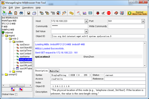
Figure 7-5-3 Get system location
After the rest field has been filled, then verify it. Click Operations->GET to get the value of system location and it returns the value which we just set.
(2). Set SNMP parameters via SNMP MIB browser. For example, set the system name. system name is “dgw100x” by default, then set it as “VoIP gateway”. See figure 7-5-4.
- Click Operations->GET to attain the current system name.
- Fill the field of Set Value with “VoIP gateway”.
- Click Operations->SET to set the system name.
- Click Operations->GET to attain the modified system name.
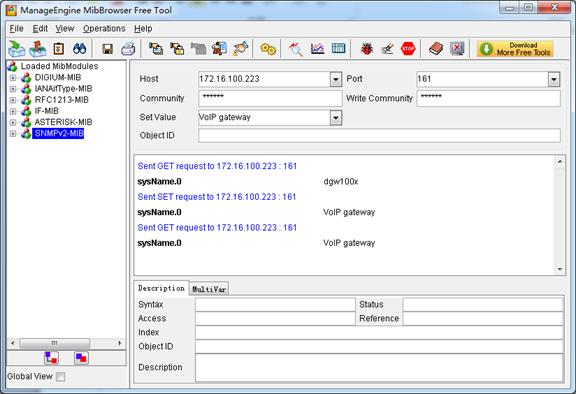
Figure 7-5-4 Set system name
TR069
TR069 is a remote management solution which offers a single interface to manage the ACS and automate the deployment and support of data, voice and video services, thereby reducing operation and support costs, while enhancing customer satisfaction. Its user-friendly interface covers the entire service lifecycle, from centralized remote provisioning of services, to inventory management, group updates, monitoring, event triggering, and support automation. Figure 7-6-1 is TR-069 configuration interface and table 7-6-1 is its definition.
Table 7-6-1 Definition of TR069 configuration interface
Options | Definition |
Acs Url | Specify the URL of the ACS |
Acs Username | Specify the user name to be used by the device to authenticate with the ACS. |
Acs Password | Specify the password to be used by the device to authenticate with the file server |
Provisioning Code | Information of the device vendor, which may be used to indicate the primary service provider and other provisioning information to the ACS. It can be numbers or English letters. |
Model Name | A brief description of the interface type or name. It is a string of characters. |
Periodic Enable | Used to specify whether to periodically report to the ACS. |
Periodic Interval | The interval for reporting to the ACS. |
Connection Request Url | The address used for the ACS to connect back to the device. |
Connection Request Username | The account used for the ACS to connect back to the device, for example, admin. |
Connection Request Password | The password used for the network management server to connect back to the device. |
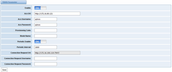
Figure 7-6-1 TR069 configuration interface
Network Capture
The gateway have been supplied a network packets capture in the web for ease of user to analysis, capture and monitor the gateway’s network status, RTP flows, protocol analysis and so on.
Table 7-7-1 Definition of Network capture
Options | Definition |
Network Interface | Specify which interface to be capture packets from. ‘All’ means capture packets from all interfaces |
Source host | Specify which source host IP address to listen for |
Destination host | Specify which destination host IP address to listen for |
Port | To specify a port that is either source or destination direction |
Protocol | To specify which protocol to be captured, ‘All’ stands for capture multi-protocols, the SIP default port is 5060, If you are using a different port, please amend it. |
The interface is in ADVANCED->Network Capture.
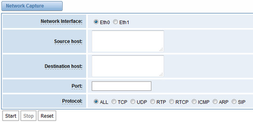
Figure 7-7-1 Network capture interface
8. Logs
On the “Log Settings” page, you should set the related logs on to scan the responding logs page. For example, set “SIP Logs” on like the following, then you can turn to “SIP” page for sip logs, otherwise, sip logs is unavailable. And the same with other log pages.
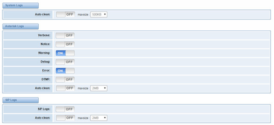
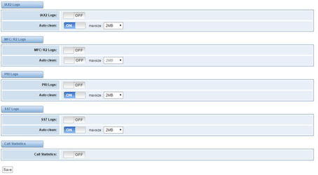
Figure 8-1-1 Logs Settings
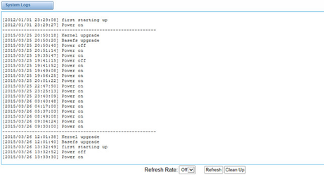
Figure 8-1-2 System Logs Output
...
Options | Definition | ||||
Auto clean: (System Logs) | switch on : when the size of log file reaches the max size, the system will cut a half of the file. New logs will be retained. switch off : logs will remain, and the file size will increase gradually. default on, default size=1MB | ||||
Verbose: | Asterisk console verbose message switch. | ||||
Notice: | Asterisk console notice message switch. | ||||
Warning: | Asterisk console warning message switch. | ||||
Debug: | Asterisk console debug message switch. | ||||
Error: | Asterisk console error message switch. | ||||
DTMF: | Asterisk console DTMF info switch. | ||||
Auto clean: (asterisk logs) | switch on : when the size of log file reaches the max size, the system will cut a half of the file. New logs will be retained. Switch off: logs will remain, and the file size will increase gradually. default on, default size=100KB2MB | ||||
SIP Logs: | Whether enable or disable SIP log. | ||||
Auto clean: (SIP logs) | switch on : when the size of log file reaches the max size, the system will cut a half of the file. New logs will be retained. Switch off: logs will remain, and the file size will increase gradually. default on, default size=2MB | ||||
IAX2 Logs | Whether enable or disable IAX log | ||||
Auto clean | switch on : when the size of log file reaches the max size, the system will cut a half of the file. New logs will be retained. Switch off: logs will remain, and the file size will increase gradually. default on, default size=2MB | ||||
MFC/ R2 Logs | Whether enable or disable MFC/ R2 Logs log. | Auto clean | Whether enable or disable MFC/ R2 Logs log. | ||
Auto clean | switch on : when the size of log file reaches the max size, the system will cut a half of the file. New logs will be retained. Switch off: logs will remain, and the file size will increase gradually. default on, default size=2MB | ||||
PRI Logs | PRI port logs. You can choose one or more ports. If you choose "All", the "PRI" page will show you the logs about all the ports. | ||||
Auto clean (PRI logs) | switch on : when the size of log file reaches the max size, the system will cut a half of the file. New logs will be retained. Switch off: logs will remain, and the file size will increase gradually. default on,default size= 100KB | ||||
PRI Logs | PRI port logs. You can choose one or more ports. If you choose "All", the "PRI" page will show you the logs about all the ports. | ||||
On the “Log Settings” page, you should set the related logs on to scan the responding logs page. For example, set “SIP Logs” on like the following, then you can turn to “SIP” page for sip logs, otherwise, sip logs is unavailable. And the same with other log pages. | |||||
.SS7 Logs | Whether enable or disable SS7 log | ||||
Auto clean | switch on : when the size of log file reaches the max size, the system will cut a half of the file. New logs will be retained. Switch off: logs will remain, and the file size will increase gradually. default on, default size=2MB | ||||
Call Statistics | Whether enable or disable Call Statistics. | ||||
System log
System log record every time power on, power off and firmware upgrade information.
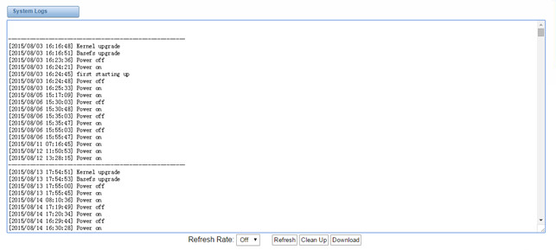
Figure 8-2-1 System Log
Asterisk logs
On the pages of “Asterisk”, “SIP”, “IAX2”, “SS7”, “PRI” and “MFC/R2”, there owns the some functions—Displays the log by port,
...
default on, default size=2MB
...
.SS7 Logs
...
Whether enable or disable SS7 log
...
Auto clean
...
switch on : when the size of log file reaches the max size,
the system will cut a half of the file. New logs will be retained.
Switch off: logs will remain, and the file size will increase gradually.
default on, default size=100KB
...
Call Statistics
...
Whether enable or disable Call Statistics.
...
System
Figure 8-2-1 System Logs
Asterisk
Figure 8-3-1 Asterisk Logs
On the pages of “system”, ”Asterisk”, “SIP”, “IAX2”, “SS7”, and “MFC/R2”, there are some functions: Displays the log by port, refresh regularly and log download.
Statistics
Figure 8-9-1 Call Statistics
The figure of call statistics, you’ll find “Answered” “congestion” “busy” “failed” “no answer” refresh regularly and log download.
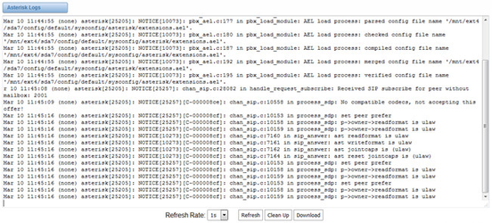
Figure 8-3-1 Asterisk Log
Call Statistics
The figure of call statistics, you’ll find “Answered”, “congestion”, “Call busy”, “Call failed”, “No answer”, “Current calls”, “accumulated calls”, “Calls duration” and “ASR”. “ASR” stands for Answer Seizure Ratio. “Calls duration” will count the whole calls in the gateway. The call statistics will be saved before power off. It will be loaded after power on. It can be refreshed by itself. You can reset the statistics manually.
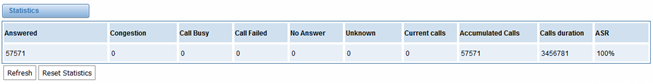
Figure 8-4-1 Call Statistics
Note: Do not forget to enable call statistics in “Log Setting” if you want to statistics the calls.
System Notice
The system notice could be generated by system to inform the network manager of what is going on if it has been enabled. Firmware upgrade messages from official website and auto provisioning messages from ACS are main notice right now. And at first, enable the system notice function like figure 8-5-1.
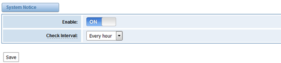
Figure 8-5-1 enable system notice function
After about an hour, a system message is received in the web like 8-5-2.
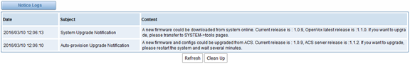
Figure 8-5-2 enable system notice function
Note: Do not forget to enable system notice and check interval in “Log Setting” if you want to receive system messages.